This thread has been locked.

If you have a related question, please click the "Ask a related question" button in the top right corner. The newly created question will be automatically linked to this question.

TM4C1294NCPDT: TM4C1294 EVK

Part Number: TM4C1294NCPDT
Other Parts Discussed in Thread: EK-TM4C1294XL

Hi Team,

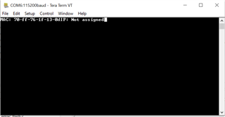
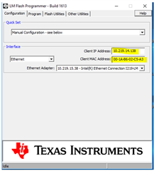
I am using TM4C1294 EVK , here i am  trying to flash the .hex file via ethernet firmware upgrade, I could able to write the hex file to flash via ethernet, using TCP IP with external application to load the binary from laptop

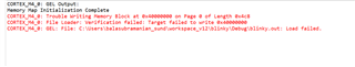
but the Ethernet also write the junk values form other application like (chrome) when it is open , along with hex file 

can you suggest how can fix this 

can you also help us to share any working example code for ethernet Firmware upgrade along with or without bootloader using TCP IP packets  for TM4C1294 EVK 

please help us with working sample example projects and documents for ethernet firmware upgrade 

please response ASAP

  • I could able to write the hex file to flash via ethernet, using TCP IP with external application to load the binary from laptop

    What external application are you using? You can use LM flash programmer or command-line C:\ti\TivaWare_C_Series-2.2.0.295\tools\bin\eflash.exe to download your firmware to the flash via Ethernet. If you are using a 3rd party tool then I can't support it. Please understand. 

    can you also help us to share any working example code for ethernet Firmware upgrade along with or without bootloader using TCP IP packets  for TM4C1294 EVK 

    We have Ethernet bootloader examples. You can find the bootloader which is a small piece of firmware residing at 0x0 on the flash. The bootloader example CCS project can be found at C:\ti\TivaWare_C_Series-2.2.0.295\examples\boards\ek-tm4c1294xl\boot_emac_flash. There is another application example that goes along with the bootloader. The application example can be found at C:\ti\TivaWare_C_Series-2.2.0.295\examples\boards\ek-tm4c1294xl\boot_demo_emac_flash. The bootloader (boot_emac_flash) will load the example application (boot_demo_emac_flash) through Ethernet using TCP/IP protocol. As mentioned, the download tool running on the host PC can be either LM flash programmer or eflash.exe. This pair of examples will work out of box. Why don't you first try the stock example first? I have never heard that other junk values will be mixed with the application firmware during the firmware update. 

  • Hi charles

    I tried to build the project boot_demo_emac_flash, with uart prints , Iam getting the following outputs in terminal 

    PFB image 

    PFB code please suggest what change need to be done get the IP address  or tell the procedure how to test this demo code

    //*****************************************************************************
    //
    // boot_demo_emac_flash.c - Boot Loader ethernet Demo.
    //
    // Copyright (c) 2008-2020 Texas Instruments Incorporated.  All rights reserved.
    // Software License Agreement
    // 
    // Texas Instruments (TI) is supplying this software for use solely and
    // exclusively on TI's microcontroller products. The software is owned by
    // TI and/or its suppliers, and is protected under applicable copyright
    // laws. You may not combine this software with "viral" open-source
    // software in order to form a larger program.
    // 
    // THIS SOFTWARE IS PROVIDED "AS IS" AND WITH ALL FAULTS.
    // NO WARRANTIES, WHETHER EXPRESS, IMPLIED OR STATUTORY, INCLUDING, BUT
    // NOT LIMITED TO, IMPLIED WARRANTIES OF MERCHANTABILITY AND FITNESS FOR
    // A PARTICULAR PURPOSE APPLY TO THIS SOFTWARE. TI SHALL NOT, UNDER ANY
    // CIRCUMSTANCES, BE LIABLE FOR SPECIAL, INCIDENTAL, OR CONSEQUENTIAL
    // DAMAGES, FOR ANY REASON WHATSOEVER.
    // 
    // This is part of revision 2.2.0.295 of the EK-TM4C1294XL Firmware Package.
    //
    //*****************************************************************************
    
    #include <stdbool.h>
    #include <stdint.h>
    #include "inc/hw_gpio.h"
    #include "inc/hw_memmap.h"
    #include "inc/hw_nvic.h"
    #include "inc/hw_sysctl.h"
    #include "inc/hw_types.h"
    #include "driverlib/debug.h"
    #include "driverlib/interrupt.h"
    #include "driverlib/flash.h"
    #include "driverlib/gpio.h"
    #include "driverlib/interrupt.h"
    #include "driverlib/pin_map.h"
    #include "driverlib/rom.h"
    #include "driverlib/rom_map.h"
    #include "driverlib/sysctl.h"
    #include "driverlib/uart.h"
    #include "utils/lwiplib.h"
    #include "utils/swupdate.h"
    #include "utils/ustdlib.h"
    #include "utils/uartstdio.h"
    
    //*****************************************************************************
    //
    //! \addtogroup example_list
    //! <h1>Boot Loader ethernet Demo (boot_demo_emac_flash)</h1>
    //!
    //! An example to demonstrate the use of remote update signaling with the
    //! flash-based Ethernet boot loader.  This application configures the Ethernet
    //! controller and acquires an IP address which is displayed on the screen
    //! along with the board's MAC address.  It then listens for a ``magic packet''
    //! telling it that a firmware upgrade request is being made and, when this
    //! packet is received, transfers control into the boot loader to perform the
    //! upgrade.
    //!
    //! This application is intended for use with flash-based ethernet boot
    //! loader (boot_emac).
    //! 
    //! The link address for this application is set to 0x4000, the link address
    //! has to be multiple of the flash erase block size(16KB=0x4000).
    //! You may change this address to a 16KB boundary higher than the last
    //! address occupied by the boot loader binary as long as you also rebuild the
    //! boot loader itself after modifying its bl_config.h file to set
    //! APP_START_ADDRESS to the same value.
    //!
    //! The boot_demo_flash application can be used along with this application to
    //! easily demonstrate that the boot loader is actually updating the on-chip
    //! flash.
    //
    //*****************************************************************************
    
    //*****************************************************************************
    //
    // The number of SysTick ticks per second.
    //
    //*****************************************************************************
    #define TICKS_PER_SECOND 100
    
    //*****************************************************************************
    //
    // A global flag used to indicate if a remote firmware update request has been
    // received.
    //
    //*****************************************************************************
    static volatile bool g_bFirmwareUpdate = false;
    
    //*****************************************************************************
    //
    // Buffers used to hold the Ethernet MAC and IP addresses for the board.
    //
    //*****************************************************************************
    #define SIZE_MAC_ADDR_BUFFER 32
    #define SIZE_IP_ADDR_BUFFER 32
    char g_pcMACAddr[SIZE_MAC_ADDR_BUFFER];
    char g_pcIPAddr[SIZE_IP_ADDR_BUFFER];
    
    //*****************************************************************************
    //
    // A global we use to update the system clock frequency
    //
    //*****************************************************************************
    volatile uint32_t g_ui32SysClock;
    void
    InitConsole(void);
    //*****************************************************************************
    //
    // The error routine that is called if the driver library encounters an error.
    //
    //*****************************************************************************
    #ifdef DEBUG
    void
    __error__(char *pcFilename, uint32_t ui32Line) 
    {
    }
    #endif
    
    //*****************************************************************************
    //
    // This is the handler for this SysTick interrupt.  We use this to provide the
    // required timer call to the lwIP stack.
    //
    //*****************************************************************************
    void
    SysTickIntHandler(void)
    {
        //
        // Call the lwIP timer.
        //
        lwIPTimer(1000 / TICKS_PER_SECOND);
    }


    void
    InitConsole(void)
    {
        //
        // Enable GPIO port A which is used for UART0 pins.
        // TODO: change this to whichever GPIO port you are using.
        //
        SysCtlPeripheralEnable(SYSCTL_PERIPH_GPIOA);
    
        //
        // Configure the pin muxing for UART0 functions on port A0 and A1.
        // This step is not necessary if your part does not support pin muxing.
        // TODO: change this to select the port/pin you are using.
        //
        GPIOPinConfigure(GPIO_PA0_U0RX);
        GPIOPinConfigure(GPIO_PA1_U0TX);
    
        //
        // Enable UART0 so that we can configure the clock.
        //
        SysCtlPeripheralEnable(SYSCTL_PERIPH_UART0);
    
        //
        // Use the internal 16MHz oscillator as the UART clock source.
        //
        UARTClockSourceSet(UART0_BASE, UART_CLOCK_PIOSC);
    
        //
        // Select the alternate (UART) function for these pins.
        // TODO: change this to select the port/pin you are using.
        //
        GPIOPinTypeUART(GPIO_PORTA_BASE, GPIO_PIN_0 | GPIO_PIN_1);
    
        //
        // Initialize the UART for console I/O.
        //
        UARTStdioConfig(0, 115200, 16000000);
    }
    
    //*****************************************************************************
    //
    // Initialize UART0 and set the appropriate communication parameters.
    //
    //*****************************************************************************
    void
    SetupForUART(void)
    {
        //
        // We need to make sure that UART0 and its associated GPIO port are
        // enabled before we pass control to the boot loader.  The serial boot
        // loader does not enable or configure these peripherals for us if we
        // enter it via its SVC vector.
        //
        MAP_SysCtlPeripheralEnable(SYSCTL_PERIPH_UART0);
        MAP_SysCtlPeripheralEnable(SYSCTL_PERIPH_GPIOA);
    
        //
        // Set GPIO PA0 and PA1 as UART.
        //
        MAP_GPIOPinConfigure(GPIO_PA0_U0RX);
        MAP_GPIOPinConfigure(GPIO_PA1_U0TX);
        MAP_GPIOPinTypeUART(GPIO_PORTA_BASE, GPIO_PIN_0 | GPIO_PIN_1);
    
        //
        // Configure the UART for 115200, n, 8, 1
        //
        MAP_UARTConfigSetExpClk(UART0_BASE, g_ui32SysClock, 115200,
                                (UART_CONFIG_PAR_NONE | UART_CONFIG_STOP_ONE |
                                 UART_CONFIG_WLEN_8));
    
        //
        // Enable the UART operation.
        //
        MAP_UARTEnable(UART0_BASE);
    }
    
    //*****************************************************************************
    //
    // This function is called by the software update module whenever a remote
    // host requests to update the firmware on this board.  We set a flag that
    // will cause the main loop to exit and transfer control to the bootloader.
    //
    // IMPORTANT:
    // Note that this callback is made in interrupt context and, since it is not
    // permitted to transfer control to the boot loader from within an interrupt,
    // we can't just call SoftwareUpdateBegin() here.
    //
    //*****************************************************************************
    void SoftwareUpdateRequestCallback(void)
    {
        g_bFirmwareUpdate = true;
    }
    
    //*****************************************************************************
    //
    // Perform the initialization steps required to start up the Ethernet controller
    // and lwIP stack.
    //
    //*****************************************************************************
    void
    SetupForEthernet(void)
    {
        uint32_t ui32User0, ui32User1;
        uint8_t pui8MACAddr[6];
    
        //
        // Configure SysTick for a 100Hz interrupt.
        //
        MAP_SysTickPeriodSet(g_ui32SysClock / TICKS_PER_SECOND);
        MAP_SysTickEnable();
        MAP_SysTickIntEnable();
    
        //
        // Get the MAC address from the UART0 and UART1 registers in NV ram.
        //
        MAP_FlashUserGet(&ui32User0, &ui32User1);
    
        //
        // Convert the 24/24 split MAC address from NV ram into a MAC address
        // array.
        //
        pui8MACAddr[0] = ui32User0 & 0xff;
        pui8MACAddr[1] = (ui32User0 >> 8) & 0xff;
        pui8MACAddr[2] = (ui32User0 >> 16) & 0xff;
        pui8MACAddr[3] = ui32User1 & 0xff;
        pui8MACAddr[4] = (ui32User1 >> 8) & 0xff;
        pui8MACAddr[5] = (ui32User1 >> 16) & 0xff;
    
        //
        // Format this address into the string used by the relevant widget.
        //
        UARTprintf(
                  "MAC: %02X-%02X-%02X-%02X-%02X-%02X",
                  pui8MACAddr[0], pui8MACAddr[1], pui8MACAddr[2], pui8MACAddr[3],
                  pui8MACAddr[4], pui8MACAddr[5]);
    
        //
        // Remember that we don't have an IP address yet.
        //
        UARTprintf("IP: Not assigned");
    
        //
        // Initialize the lwIP TCP/IP stack.
        //
        lwIPInit(g_ui32SysClock, pui8MACAddr, 0, 0, 0, IPADDR_USE_DHCP);
    
        //
        // Start the remote software update module.
        //
        SoftwareUpdateInit(SoftwareUpdateRequestCallback);
    }
    
    //*****************************************************************************
    //
    // Enable the USB controller
    //
    //*****************************************************************************
    void
    SetupForUSB(void)
    {
        //
        // The USB boot loader takes care of all required USB initialization so,
        // if the application itself doesn't need to use the USB controller, we
        // don't actually need to enable it here.  The only requirement imposed by
        // the USB boot loader is that the system clock is running from the PLL
        // when the boot loader is entered.
        //
    }
    
    //*****************************************************************************
    //
    // A simple application demonstrating use of the boot loader,
    //
    //*****************************************************************************
    int
    main(void)
    {
        //
        // Enable lazy stacking for interrupt handlers.  This allows floating-point
        // instructions to be used within interrupt handlers, but at the expense of
        // extra stack usage.
        //
        MAP_FPULazyStackingEnable();
    
        //
        // Run from the PLL at 120 MHz.
        // Note: SYSCTL_CFG_VCO_240 is a new setting provided in TivaWare 2.2.x and
        // later to better reflect the actual VCO speed due to SYSCTL#22.
        //
        g_ui32SysClock = MAP_SysCtlClockFreqSet((SYSCTL_XTAL_25MHZ |
                                                 SYSCTL_OSC_MAIN |
                                                 SYSCTL_USE_PLL |
                                                 SYSCTL_CFG_VCO_240), 120000000);
    
        //
        // Initialize the peripherals that each of the boot loader flavours
        // supports.  Since this example is intended for use with any of the
        // boot loaders and we don't know which is actually in use, we cover all
        // bases and initialize for serial, Ethernet and USB use here.
        //
        InitConsole();
        //SetupForUART();
        SetupForEthernet();
        //SetupForUSB();
    
        //
        // Configure Port N pin 1 as output.
        //
        MAP_SysCtlPeripheralEnable(SYSCTL_PERIPH_GPION);
        while(!(MAP_SysCtlPeripheralReady(SYSCTL_PERIPH_GPION)));
        MAP_GPIOPinTypeGPIOOutput(GPIO_PORTN_BASE, GPIO_PIN_1);
    
        //
        // If the Switch SW1 is not pressed then blink the LED D1 at 1 Hz rate
        // On switch SW press detection exit the blinking program and jump to
        // the flash boot loader.
        //
        while(!g_bFirmwareUpdate)
        {
            MAP_GPIOPinWrite(GPIO_PORTN_BASE, GPIO_PIN_1, 0x0);
            MAP_SysCtlDelay(g_ui32SysClock / 6);
            MAP_GPIOPinWrite(GPIO_PORTN_BASE, GPIO_PIN_1, GPIO_PIN_1);
            MAP_SysCtlDelay(g_ui32SysClock / 6);
        }
    
        //
        // Before passing control make sure that the LED is turned OFF.
        //
        MAP_GPIOPinWrite(GPIO_PORTN_BASE, GPIO_PIN_1, 0x0);
        
        //
        // Pass control to whichever flavour of boot loader the board is configured
        // with.
        //
        SoftwareUpdateBegin(g_ui32SysClock);
    
        //
        // The previous function never returns but we need to stick in a return
        // code here to keep the compiler from generating a warning.
        //
        return(0);
    }
    

  • Hi,

      Let me suppose you use the LM flash programmer to update your firmware. But the idea will be the same for other tools to use, e.g. eflash.exe.  In the LM flash programmer you would need to specify the Client IP address and MAC address. Did you do this? The stock TivaWare bootloader is a very light-weight stack that does not contain DHCP application layer (an OSI layer 7) code. Neither is the boot_demo_emac_flash. To enter the IP address to LM flash programmer, you will need to run a different example like the enet_lwip or enet_io or any of the example that will acquire an IP address.  Once you obtain the IP address, you will enter it in LM flash programmer for your bootloader example. The reason is that the DHCP IP address is normally leased to you by the DHCP server on your network. The IP address will remain for a certain period of time. That IP address and MAC address pair must be entered to LM flash programmer acting as a BootP/TFTP server. 

      I strongly suggest you first run the stock examples; boot_emac_flash as the bootloader and boot_demo_emac_flash as the application firmware on a LaunchPad. Make sure it works before you move on to your custom bootloader.

  • FW is transferred  to TM4c via TCP of application code and stored in secondary memory. Once successful transfer of FW, the system has to boot with new FW.

    For that there are 2 options, option1-restart with new FW address; option 2 - restart to boot code, check for FW upgrade flag and flash the Application start address from secondary memory and clear the FW upgrade flag and restart again.

    To explore these 2 option. We have tried to load the boot (BOOT) in flash start address, and application (APP) in another address of flash. We could able to debug both the application separately via CCS tool.

    I wanted to switch the from BOOT to APP: I have tried to reconfigure the NVIC register (HWREG(NVIC_VTABLE)) with

    • APP address -> HWREG(NVIC_VTABLE) = 0x00002838; (or) 
    • init function of APP -> HWREG(NVIC_VTABLE) = 0x00002aa1;

    __asm(" ldr r1, [r0]\n"
    " mov sp, r1");

     __asm(" ldr r0, [r0, #4]\n"
     " bx r0\n");

    But reset_ISR is called but not switching to APP when HWREG of NVIC is done.

    Tried with the "(*((void (*)(void)) (*(uint32_t *) 0x00002838)))();". error "Break at address "0xfffffffe" with no debug information available, or outside of program code." is shown.

    Please suggest me the method to switching from boot to app and what are the changes needed in both cmd files.

    cmd file in boot:


    --retain=g_pfnVectors

    /* The starting address of the application. Normally the interrupt vectors */
    /* must be located at the beginning of the application. */
    #define APP_BASE 0x00000000
    #define RAM_BASE 0x20000000

    /* System memory map */

    MEMORY
    {
    /* Application stored in and executes from internal flash */
    FLASH (RX) : origin = APP_BASE, length = 0x00002000
    FLASH_APP1 (RWX) : origin = 0x00002838, length = 0x00002000
    FLASH_APP2 (RWX) : origin = 0x00006578, length = 0x00002000

    /* Application uses internal RAM for data */
    SRAM (RWX) : origin = 0x20000000, length = 0x00040000
    }

    /* Section allocation in memory */

    SECTIONS
    {
    .intvecs: > APP_BASE
    .text : > FLASH
    .const : > FLASH
    .cinit : > FLASH
    .pinit : > FLASH
    .init_array : > FLASH

    .vtable : > RAM_BASE
    .data : > SRAM
    .bss : > SRAM
    .sysmem : > SRAM
    .stack : > SRAM
    #ifdef __TI_COMPILER_VERSION__
    #if __TI_COMPILER_VERSION__ >= 15009000
    .TI.ramfunc : {} load=FLASH, run=SRAM, table(BINIT)
    #endif
    #endif
    }

    __STACK_TOP = __stack + 512;

    cmd file in App

    --retain=g_pfnVectors

    /* The starting address of the application. Normally the interrupt vectors */
    /* must be located at the beginning of the application. */
    #define APP_BASE 0x00000000
    #define RAM_BASE 0x20000000

    /* System memory map */

    MEMORY
    {
    /* Application stored in and executes from internal flash */
    FLASH (RX) : origin = APP_BASE, length = 0x00002000
    FLASH_APP1 (RWX) : origin = 0x00002838, length = 0x00002000
    FLASH_APP2 (RWX) : origin = 0x00006578, length = 0x00002000

    /* Application uses internal RAM for data */
    SRAM (RWX) : origin = 0x20000000, length = 0x00040000
    }

    /* Section allocation in memory */

    SECTIONS
    {
    .intvecs: > FLASH_APP1
    .text : > FLASH_APP1
    .const : > FLASH_APP1
    .cinit : > FLASH_APP1
    .pinit : > FLASH_APP1
    .init_array : > FLASH_APP1

    .vtable : > RAM_BASE
    .data : > SRAM
    .bss : > SRAM
    .sysmem : > SRAM
    .stack : > SRAM
    #ifdef __TI_COMPILER_VERSION__
    #if __TI_COMPILER_VERSION__ >= 15009000
    .TI.ramfunc : {} load=FLASH_APP1, run=SRAM, table(BINIT)
    #endif
    #endif
    }

    __STACK_TOP = __stack + 512;

  • MEMORY
    {
    /* Application stored in and executes from internal flash */
    FLASH (RX) : origin = APP_BASE, length = 0x00002000
    FLASH_APP1 (RWX) : origin = 0x00002838, length = 0x00002000
    FLASH_APP2 (RWX) : origin = 0x00006578, length = 0x00002000

    /* Application uses internal RAM for data */
    SRAM (RWX) : origin = 0x20000000, length = 0x00040000

    Several comments:

    - Your FW is really only 8kB each? That sounds quite small but it your application. I'm just curious.

    - Your FW does not start at a multiple of 1024 bytes. The starting address must be aligned to a flash page boundary. 0x2838 iand 0x6578 is not aligned to to flash page boundary. Why don't you make FW1 0x4000 and FW2 0x8000. Refer to bl_config.h file. See below. 

    //*****************************************************************************
    //
    // The starting address of the application.  This must be a multiple of 1024
    // bytes (making it aligned to a page boundary).  A vector table is expected at
    // this location, and the perceived validity of the vector table (stack located
    // in SRAM, reset vector located in flash) is used as an indication of the
    // validity of the application image.
    //
    // The flash image of the boot loader must not be larger than this value.
    //
    // Depends on: None
    // Exclusive of: None
    // Requires: None
    //
    //*****************************************************************************
    #define APP_START_ADDRESS       0x00004000
    
    //*****************************************************************************
    //
    // The address at which the application locates its exception vector table.
    // This must be a multiple of 1024 bytes (making it aligned to a page
    // boundary).  Typically, an application will start with its vector table and
    // this value should be set to APP_START_ADDRESS.  This option is provided to
    // cater for applications which run from external memory which may not be
    // accessible by the NVIC (the vector table offset register is only 30 bits
    // long).
    //
    // Depends on: None
    // Exclusive of: None
    // Requires: None
    //
    //*****************************************************************************
    #define VTABLE_START_ADDRESS    0x00004000

     - The bootloader must know where the FW starts. In the bl_config.h file for the stock boot_emac_flash example, the APP_START_ADDRESS is 0x4000. This address must be the same as where your FW is linked to. As noted, 0x2838 is not a correct boundary. Even if it is ok, you must change APP_START_ADDRESS so the bootloader knows where to jump from BOOT to APP.

     - The example only recognizes one FW starting address. Since you have two FWs, you must add intelligence to the bootloader so it knows when to jump to FW1 or FW2. As it is right now, it will jump to whatever starting address as defined in APP_START_ADDRESS. 

  • When I tried to chnage the firmware address to 0x40000000

    iam getting following error 

    Hi this is my .cmd file can you please change what adress value to changed and please revert back 

    /******************************************************************************
     *
     * blinky_ccs.cmd - CCS linker configuration file for blinky.
     *
     * Copyright (c) 2013-2020 Texas Instruments Incorporated.  All rights reserved.
     * Software License Agreement
     * 
     * Texas Instruments (TI) is supplying this software for use solely and
     * exclusively on TI's microcontroller products. The software is owned by
     * TI and/or its suppliers, and is protected under applicable copyright
     * laws. You may not combine this software with "viral" open-source
     * software in order to form a larger program.
     * 
     * THIS SOFTWARE IS PROVIDED "AS IS" AND WITH ALL FAULTS.
     * NO WARRANTIES, WHETHER EXPRESS, IMPLIED OR STATUTORY, INCLUDING, BUT
     * NOT LIMITED TO, IMPLIED WARRANTIES OF MERCHANTABILITY AND FITNESS FOR
     * A PARTICULAR PURPOSE APPLY TO THIS SOFTWARE. TI SHALL NOT, UNDER ANY
     * CIRCUMSTANCES, BE LIABLE FOR SPECIAL, INCIDENTAL, OR CONSEQUENTIAL
     * DAMAGES, FOR ANY REASON WHATSOEVER.
     * 
     * This is part of revision 2.2.0.295 of the EK-TM4C1294XL Firmware Package.
     *
     *****************************************************************************/
    
    --retain=g_pfnVectors
    
    /* The following command line options are set as part of the CCS project.    */
    /* If you are building using the command line, or for some reason want to    */
    /* define them here, you can uncomment and modify these lines as needed.     */
    /* If you are using CCS for building, it is probably better to make any such */
    /* modifications in your CCS project and leave this file alone.              */
    /*                                                                           */
    /* --heap_size=0                                                             */
    /* --stack_size=256                                                          */
    /* --library=rtsv7M3_T_le_eabi.lib                                           */
    
    /* The starting address of the application.  Normally the interrupt vectors  */
    /* must be located at the beginning of the application.                      */
    #define APP_BASE 0x40000000
    #define RAM_BASE 0x20000000
    
    /* System memory map */
    
    MEMORY
    {
        /* Application stored in and executes from internal flash */
        FLASH (RWX) : origin = APP_BASE, length = 0x00002000
    	//FLASH_APP1 (RWX)    : origin = 0x00002838, length = 0x00002000
    	//FLASH_APP2 (RWX)    : origin = 0x00006578, length = 0x00002000
    
        /* Application uses internal RAM for data */
        SRAM (RWX) : origin = 0x20000000, length = 0x00040000
    }
    
    /* Section allocation in memory */
    
    SECTIONS
    {
        .intvecs:   > APP_BASE
        .text   :   > FLASH
        .const  :   > FLASH
        .cinit  :   > FLASH
        .pinit  :   > FLASH
        .init_array : > FLASH
    
        .vtable :   > RAM_BASE
        .data   :   > SRAM
        .bss    :   > SRAM
        .sysmem :   > SRAM
        .stack  :   > SRAM
    #ifdef  __TI_COMPILER_VERSION__
    #if     __TI_COMPILER_VERSION__ >= 15009000
        .TI.ramfunc : {} load=FLASH, run=SRAM, table(BINIT)
    #endif
    #endif
    }
    
    __STACK_TOP = __stack + 4096;
    

    Also I attached the application code I exactly don't know how to switch the pointer can you please check the code and revert back

    can you help me to fix the issue

    //*****************************************************************************
    //
    // blinky.c - Simple example to blink the on-board LED.
    //
    // Copyright (c) 2013-2020 Texas Instruments Incorporated.  All rights reserved.
    // Software License Agreement
    // 
    // Texas Instruments (TI) is supplying this software for use solely and
    // exclusively on TI's microcontroller products. The software is owned by
    // TI and/or its suppliers, and is protected under applicable copyright
    // laws. You may not combine this software with "viral" open-source
    // software in order to form a larger program.
    // 
    // THIS SOFTWARE IS PROVIDED "AS IS" AND WITH ALL FAULTS.
    // NO WARRANTIES, WHETHER EXPRESS, IMPLIED OR STATUTORY, INCLUDING, BUT
    // NOT LIMITED TO, IMPLIED WARRANTIES OF MERCHANTABILITY AND FITNESS FOR
    // A PARTICULAR PURPOSE APPLY TO THIS SOFTWARE. TI SHALL NOT, UNDER ANY
    // CIRCUMSTANCES, BE LIABLE FOR SPECIAL, INCIDENTAL, OR CONSEQUENTIAL
    // DAMAGES, FOR ANY REASON WHATSOEVER.
    // 
    // This is part of revision 2.2.0.295 of the EK-TM4C1294XL Firmware Package.
    //
    //*****************************************************************************
    
    #include <stdint.h>
    #include <stdbool.h>
    #include "inc/hw_memmap.h"
    #include "driverlib/debug.h"
    #include "driverlib/gpio.h"
    #include "driverlib/sysctl.h"
    #include <stdint.h>
    #include <stdbool.h>
    #include "inc/hw_gpio.h"
    #include "inc/hw_flash.h"
    #include "inc/hw_i2c.h"
    #include "inc/hw_memmap.h"
    #include "inc/hw_nvic.h"
    #include "inc/hw_ssi.h"
    #include "inc/hw_sysctl.h"
    #include "inc/hw_types.h"
    #include "inc/hw_uart.h"
    #include "driverlib/uart.h"
    #include "driverlib/rom.h"
    //*****************************************************************************
    //
    //! \addtogroup example_list
    //! <h1>Blinky (blinky)</h1>
    //!
    //! A very simple example that blinks the on-board LED using direct register
    //! access.
    //
    //*****************************************************************************
    
    //*****************************************************************************
    //
    // The error routine that is called if the driver library encounters an error.
    //
    //*****************************************************************************
    #ifdef DEBUG
    void
    __error__(char *pcFilename, uint32_t ui32Line)
    {
        while(1);
    }
    #endif
    
    //*****************************************************************************
    //
    // Blink the on-board LED.
    //
    //*****************************************************************************
    int
    main(void)
    {
    
        bool FWUp = true;
       if(FWUp == true)
       {
           (*((void (*)(void)) (*(uint32_t *)  0x00002aa1)))();
    
           HWREG(NVIC_VTABLE) = 0x00002aa1;
    
    //    // Load the stack pointer from the application's vector table.
    
       __asm(" ldr r1, [r0]\n"
       " mov sp, r1");
    
    //    // Load the initial PC from the application's vector table and branch to
    //    // the application's entry point.
    
       __asm(" ldr r0, [r0, #4]\n"
       " bx r0\n");
    
        }
    
        while(1)
        {
    
        }
    }
    

    can you please check these file and revert back me with changes 

    and please tell the (.bin) test binary address to be modified

    if possible can you also send me test binary .cmd file 

  • When I tried to chnage the firmware address to 0x40000000

    Why are you setting the APP starting address to 0x40000000? This is at 1GB. The MCU only has 1MB of flash memory. You are setting an APP starting address that is beyond the valid memory space. I asked you to use 0x4000. What is the reason you cannot use 0x4000?