This thread has been locked.

If you have a related question, please click the "Ask a related question" button in the top right corner. The newly created question will be automatically linked to this question.

TM4C1294NCPDT: Booting of application after upgrade

Part Number: TM4C1294NCPDT
Other Parts Discussed in Thread: UNIFLASH, EK-TM4C1294XL

In my device, the FW upgrade has to be done via ethernet by another device. So I have created code in my application (start address 0x20000) to received data via TCP/IP and flashing into another memory (0x40000). and setting FW upgrade flag as 1 in configuration memory.

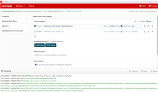
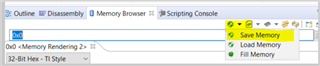
I have checked the stored data in 0x40000 is same as the binary loaded from PC tool (project tool). 

App:

1. TCP/IP

2. FW upgrade command receives, store data in 0x40000 

3. check for CRCs and set FW upgrade flag

4. move to boot address (0x00)

code used to move to boot address

HWREG(NVIC_VTABLE) = 0x00;

// Load the stack pointer from the application's vector table.
__asm(" ldr r1, [r0]\n"
" mov sp, r1");

// Load the initial PC from the application's vector table and branch to
// the application's entry point.
__asm(" ldr r0, [r0, #4]\n"
" bx r0\n");

In Boot code:

1. Checking for FW upgrade flag status.

2. If fw upgrade is set, then erasing flash 0f application (0x20000 length about 128kb) and flash write data from 0x40000 to 0x20000 and reset the FW upgrade flag.

3. jump to application address 0x20000. (both FW upgrade flag set or not set). This is working when bootloader is flashed 1st and flashing application via CCS IDE / LM flash.

HWREG(NVIC_VTABLE) = 0x20000;

// Load the stack pointer from the application's vector table.
__asm(" ldr r1, [r0]\n"
" mov sp, r1");

// Load the initial PC from the application's vector table and branch to
// the application's entry point.
__asm(" ldr r0, [r0, #4]\n"
" bx r0\n");

After upgrading via PC tool (project tool), flashing from 0x40000 to 0x20000 and jump to application is not working. Is anyother is missing in jumping to location. both boot and application using same SRAM - 0x20000000 memory. Do I need to change anything in SRAM.

App Cmd file


--retain=g_pfnVectors

/* The following command line options are set as part of the CCS project. */
/* If you are building using the command line, or for some reason want to */
/* define them here, you can uncomment and modify these lines as needed. */
/* If you are using CCS for building, it is probably better to make any such */
/* modifications in your CCS project and leave this file alone. */
/* */
/* --heap_size=0 */
/* --stack_size=256 */
/* --library=rtsv7M3_T_le_eabi.lib */

/* The starting address of the application. Normally the interrupt vectors */
/* must be located at the beginning of the application. */
#define APP_BASE 0x00020000
#define RAM_BASE 0x20000000

/* System memory map */

MEMORY
{
/* Application stored in and executes from internal flash */
FLASH (RX) : origin = APP_BASE, length = 0x00010000
/* Application uses internal RAM for data */
SRAM (RWX) : origin = RAM_BASE, length = 0x00040000
}

/* Section allocation in memory */

SECTIONS
{
.intvecs: > APP_BASE
.text : > FLASH
.const : > FLASH
.cinit : > FLASH
.pinit : > FLASH
.init_array : > FLASH

.vtable : > RAM_BASE
.data : > SRAM
.bss : > SRAM
.sysmem : > SRAM
.stack : > SRAM

#ifdef __TI_COMPILER_VERSION__
#if __TI_COMPILER_VERSION__ >= 15009000
.TI.ramfunc : {} load=FLASH, run=SRAM, table(BINIT)
#endif
#endif
}

Boot cmd

--retain=g_pfnVectors

/* The following command line options are set as part of the CCS project. */
/* If you are building using the command line, or for some reason want to */
/* define them here, you can uncomment and modify these lines as needed. */
/* If you are using CCS for building, it is probably better to make any such */
/* modifications in your CCS project and leave this file alone. */
/* */
/* --heap_size=0 */
/* --stack_size=256 */
/* --library=rtsv7M3_T_le_eabi.lib */

/* The starting address of the application. Normally the interrupt vectors */
/* must be located at the beginning of the application. */
#define BOOT_BASE 0x00000000
#define RAM_BASE 0x20000000

/* System memory map */

MEMORY
{
/* Application stored in and executes from internal flash */
FLASH (RWX) : origin = BOOT_BASE, length = 0x00002000
/* Application uses internal RAM for data */
SRAM (RWX) : origin = 0x20000000, length = 0x00040000
}

/* Section allocation in memory */

SECTIONS
{
.intvecs: > BOOT_BASE
.text : > FLASH
.const : > FLASH
.cinit : > FLASH
.pinit : > FLASH
.init_array : > FLASH

.vtable : > RAM_BASE
.data : > SRAM
.bss : > SRAM
.sysmem : > SRAM
.stack : > SRAM
#ifdef __TI_COMPILER_VERSION__
#if __TI_COMPILER_VERSION__ >= 15009000
.TI.ramfunc : {} load=FLASH, run=SRAM, table(BINIT)
#endif
#endif
}

__STACK_TOP = __stack + 4096;

Both are having startup file. But Boot doesn't need startup. how to remove that vector in boot cmd.

  • Hi,

    Both are having startup file. But Boot doesn't need startup. how to remove that vector in boot cmd.

    What do you mean the bootloader does not need the startup file? The startup file for the bootloader is in C:\ti\TivaWare_C_Series-2.2.0.295\boot_loader\bl_startup_ccs.s. I normally would not recommend modifying the startup file. But please read this file carefully if you must customize it for your application. Read the file to have an understanding on how the bootlader jumps to the application and how the application jumps back to the bootloader.

    The stock bootloader checks by calling CheckForceUpdate to see if the application at APP_START_ADDRESS is 0xFFFFFFFF. CheckForceUpdate is in bl_check.c file. If there is a non-FFFFFFFF value at APP_START_ADDRESS  then the bootloader will jump to the application. The stock bootloader will jump to APP_START_ADDRESS but if you have two application images, then you need to add intelligence as to which one to jump to. 

    I don't know what happened when you program your second FW to 0x40000. What happened to the flash at 0x20000? Did you inadvertently erase your first FW? Use the memory browser to confirm if 0x20000 is still intact. If 0x20000 is somehow erased while you are trying to upgrade the second FW at 0x40000 and if your bootloader is trying to jump to the first FW at 0x20000, it has no application code to jump to and it will remain in the bootloader mode. 

    The linker command file for the bootloader is in C:\ti\TivaWare_C_Series-2.2.0.295\boot_loader\bl_link_ccs.cmd. If you read the .cmd file you will see that the load and run addresses for the bootloader. The bootloader is loaded from 0x0 but run from 0x20000000. If you read the bl_startup_ccs.s file, you will see that after the device is out of reset, it will first copy the program image from 0x0 to 0x20000000 and then change the NVIC_TABLE to 0x20000000 and then run the bootloader code from 0x20000000 which is the SRAM address. Review the ProcessorInit function in the startup file. The bootloader is used to program your application code. If the bootloader is run from 0x0 then you will have problem programming the application. It is like running code from the flash and trying to programming the flash (although at a different address) at the same time. This is why the bootloader is to be run from the SRAM and the associated vector table and stack pointer and reset vector entry point set to SRAM at 0x20000000. Reading your bootloader linker command file, it is load and run from 0x0. You only change the .intvecs to SRAM but still run bootloader code in flash. 

  • As suggested, now, I am using bl_link_ccs.cmd and bl_startup_ccs.c and Tiva bootloader. And changed the start address of app as 0x4000.

    bootloader -> 0x0 address and App 1 - 0x4000.

    Issue 1: Not working when loading binary via uniflash. (print statements added in UART for these switching of app and boot test).

    1. Loaded bootloader binary in 0x00. and application in 0x4000 via uniflash. no observation.

    2. I have loaded bootloader via CCS,  and 0x4000 had binary loaded via uniflash. Boot code executed but the application code is not working.

    3. I have loaded loaded application via CCS, application works. Powered off and powered on the eval kit able to see both code running.

    Issue 2: Not switching from application to booloader.

    1. FW upgrade has to perform via ethernet. So I have separated another flash to sore the new FW (0x20000). In application using lwip, receiving new FW binary and stored in secondary memory (0x20000). trying to switch to bootloader location, in debug mode this switching is happening but not clear whether switching is happening or only app code alone is executing.

    2. this switching is done using nvic vector. 

    HWREG(NVIC_VTABLE) = StartAddress;

    // Load the stack pointer from the application's vector table.
    __asm(" ldr r1, [r0]\n"
    " mov sp, r1");

    // Load the initial PC from the application's vector table and branch to the application's entry point.
    __asm(" ldr r0, [r0, #4]\n"
    " bx r0\n");

    While upgradation via test utility, CRC are calculated those are matching and binary stored in 0x20000 is matching with the binary loaded.

    Bootloader code has been updated to check the fw upgade flag after copytoRAM, if the flag is set, rewriting the 0x4000 memory with new FW from 0x20000. this CRC also same as expected. there is no loss of data while upgrading. trying to switch to 0x4000. This switching also not happening.

    Issue 3: interrupts are not happening after switching (not clear whether switching is happening or not as said before only with CCS debug of app code, below are observed.

    1. After switching to application from bootloader (via CCS, FW upgrade or programmer not working) without reset of the device using nvic vector set. Able to Start the application from bootloader but interrupts are not happening.

    2. Trying to disable interrupts before setting the vector address, "NVIC_INT_CTRL" and "NVIC_SYS_PRI3" has values which are not same as the value while loading application.

  • 1. Loaded bootloader binary in 0x00. and application in 0x4000 via uniflash. no observation.

    How did you load the two binary files? Did you load at the same time or separately? If you load separately then the 2nd load for the application will overwrite the flash starting at 0x0 which is where the bootloader is located. See below if you have loaded the two binaries at the same time. I loaded the boot_emac_flash and boot_demo_emac_flash.bin and I can see both being loaded successfully and also see the LED blinking which indicates the application is running. 

    2. I have loaded bootloader via CCS,  and 0x4000 had binary loaded via uniflash. Boot code executed but the application code is not working.

    Again, you may have the same issue. When you load the bootloader using CCS, it should load successfully. But when you load the application using Uniflash at 0x4000, it may have erased the flash starting at 0x0. Check your memory browser window and see if your flash starting at 0x0 still has the bootloader image. If you see all F's then it means they are erased. 

    3. I have loaded loaded application via CCS, application works. Powered off and powered on the eval kit able to see both code running.

    How did you build your application image? Is your application image linked to 0x0 or at 0x4000. If you say it it working when loaded alone then it means you have the program image linked to 0x0. The processor after reset will look for the stack pointer at 0x0 and reset vector at 0x4. Since you build your image linking it to 0x0, this is why it is working. However, if you have a bootloader starting at 0x0, how can you build your application also at 0x0? It will overwrite each other. 

    Why don't you look at the boot_demo_emac_flash linker command file. See below for C:\ti\TivaWare_C_Series-2.2.0.295\examples\boards\ek-tm4c1294xl\boot_demo_emac_flash\boot_demo_emac_flash_ccs.cmd

    /* The starting address of the application. Normally the interrupt vectors */
    /* must be located at the beginning of the application. */
    #define APP_BASE 0x00004000
    #define RAM_BASE 0x20000000

    /* System memory map */

    MEMORY
    {
    /* Application stored in and executes from internal flash */
    FLASH (RX) : origin = APP_BASE, length = 0x000fc000
    /* Application uses internal RAM for data */
    SRAM (RWX) : origin = 0x20000000, length = 0x00040000
    }

    /* Section allocation in memory */

    SECTIONS
    {
    .intvecs: > APP_BASE
    .text : > FLASH
    .const : > FLASH
    .cinit : > FLASH
    .pinit : > FLASH
    .init_array : > FLASH

    I think we should solved your issue 1 before jumping to other issues. 

  • In Uniflash neseccary pages is selected.https://e2e.ti.com/resized-image/__size/320x240/__key/communityserver-components-multipleuploadfilemanager/fdcc57ab_2D00_368c_2D00_4901_2D00_acUpload 4f_2D00_1d5315c77c50-577940-complete/necessarypage.png

    boot address selected as 0x00 while loading , app address selected as 0x4000 while loading,

    memory after upgrade via uniflash: both are having data,

    App base in code also 0x4000. Verification also passed  .

    Code is not running and tried reset also.

  • After your custom bootloader and application are loaded and if the debugger connects to the target, where is the PC (program counter)? Is it still in the bootloader or the PC has jumped to somewhere in the application at 0x4000?

    For experiment, why don't you use the the Uniflash to load the stock boot_emac_flash.bin bootloader and your application Medtronic-HHC-primary.bin? Will your application run? If it runs then it means the stock bootloader will jump to your application but your own custom bootloader does not for some reason. 

  • I am not able to upgrade fw via ethernet by using boot_emac_flash. I tried with lmflash and eflash "attempting to connect" was shown and upgrade was not happened. Led blink (waiting for ethernet upgrade) happened, if 0x4000 has 0xffffffff. 

    So only I have custom bootloader. Here modified code  is 1 function call (modified checkapplication instead of checkforceupdate) before Enterapplication call in .s file.

    In checkapplication, If fw upgrade flag is not set, check for values in 0x4000 and return 1 (same as checkforceupdate).

    If fw upgrade flag is set, copying of new fw from 0x20000 to 0x4000 and check for application in 0x4000 and return 1.

    Then call Enterapplication. This is not working even with fw upgrade flag set and not set.

  • I am analysing on the bootloader binary generated using CCS is not working.

    If I uploaded bin, which was available in SDK (boot_serial 0x0) via LMflash, and upgrade blink binary (0x4000 build in CCS) via UART in LMflash. Both bins are working.

    If I upload the boot_serial hex /bin via LMflash which I generated using CCS is not working. while upgrading the blink binary via UART, "Establishing communication with target" was shown and a error popup occurred.

    blink -> build with CCS with app_base as 0x000 -> binary uploaded via LMflash is working. Blinky project default files used .cmd file and startup_gcc.c files and latest compiler version (V20).

    Bootloader has .cmd file and gcc.s. (default files used). bl_config.h - UART flags are enable. and build the code. Hex is generated. Compiler version - v18 (default) is selected. This generated hex is used observed the same behavior and changed the compiler version to v20 (latest) and output as binary. For both the compiler observation is same.

  • I am not able to upgrade fw via ethernet by using boot_emac_flash. I tried with lmflash and eflash "attempting to connect" was shown and upgrade was not happened. Led blink (waiting for ethernet upgrade) happened, if 0x4000 has 0xffffffff. 

    I think I have some fundamental question to ask. Please just answer me some very basic questions.

    - Have you successfully run the stock boot_emac_flash (the bootloader) and boot_demo_emac_flash (the application) examples. With the flash erased, you first load boot_emac_flash via JTAG. Once the bootloader is running, are you able to download the boot_demo_emac_flash via either lmflash or eflash? (Yes or No)?

    - Suppose you are able to download the application the first time, meaning the above step is successfully. In another word, the bootloader is still at 0x0 and the application is now at 0x4000. Once the application is running, it should blink LED. Are you able to upgrade the same application again from lmflash or eflash? (Yes or No)? When you use lmflash or eflash to upgrade the firmware, it will send a magic packet to the client. The application boot_demo_emac_flash will detect the magic packet and jump to the bootloader to upgrade the firmware again. 

      It seems that you were never able to even run the examples as is successfully. This is why I must know the answers to the above questions. You seem to indicate the boot_emac_flash does not work but only your custom bootloader will work. This is where I'm confused. The examples should work out of box. I have personally run these examples many times and I never have a problem. If you have a problem even with the examples then that is to be understood what went wrong. 

    If I uploaded bin, which was available in SDK (boot_serial 0x0) via LMflash, and upgrade blink binary (0x4000 build in CCS) via UART in LMflash. Both bins are working.

    ok. That is expected.

    If I upload the boot_serial hex /bin via LMflash which I generated using CCS is not working. while upgrading the blink binary via UART, "Establishing communication with target" was shown and a error popup occurred.

    Not sure why you need to load the hex file. In any case, can you go to the memory browser at 0x0 and show the flash content after the hex is loaded vs the bin is loaded. What is the difference? Show a screenshot of each. Perhaps your hex file for the bootloader is loaded but the content is different against the bin file. If that is the case, it has something to do with how the hex is generated. 

    blink -> build with CCS with app_base as 0x000 -> binary uploaded via LMflash is working. Blinky project default files used .cmd file and startup_gcc.c files and latest compiler version (V20).

    this is expected to work. 

    Bootloader has .cmd file and gcc.s. (default files used). bl_config.h - UART flags are enable. and build the code. Hex is generated. Compiler version - v18 (default) is selected. This generated hex is used observed the same behavior and changed the compiler version to v20 (latest) and output as binary. For both the compiler observation is same.

    Refer to my answer above. View the content that is loaded to the flash for the uart booloader at 0x0. Is it the same as the content that is loaded using the bin file? In CCS, you can even do a save memory. After you load the hex file, do a save memory and do the same for the bin file. Compare the two different memory contents. What is the difference?