Other Parts Discussed in Thread: MSP432E401Y
Hello everyone,
I have existing software running on an MSP432P4 series device (MSP432P401R). Since the MSP432P4 series has been discontinued, I am hoping to migrate the software to an MSP432E4 series device (MSP432E401Y) until a more permanent solution can be found and the software can be redesigned from the ground up.
Because the existing software was written using the TI Drivers, my understanding is that changing from an MSP432P4 series device to an MSP432E4 series device should be reasonably straightforward (from a software perspective).
The existing software is based on the portable TI-Drivers FreeRTOS example project for the MSP432P401R (C:\ti\simplelink_msp432p4_sdk_3_40_00_05\examples\rtos\MSP_EXP432P401R\demos\portable\freertos\ccs\portable_MSP_EXP432P401R_freertos_ccs.projectspec). The migrated software would hypothetically based on the portable TI-Drivers FreeRTOS example project for the MSP432E401Y (C:\ti\simplelink_msp432e4_sdk_4_20_00_12\examples\rtos\MSP_EXP432E401Y\demos\portable\freertos\ccs\portable_MSP_EXP432E401Y_freertos_ccs.projectspec).
I have begun to investigate whether this migration is feasible, starting with pinout/peripheral compatibility.
The existing software uses roughly 24 GPIOs, 4 UART interfaces, 2 I2C interfaces, 1 SPI interface, and 6 ADC inputs. The MSP432E401Y is compatible in terms of its peripherals: there are sufficient GPIO, UART, I2C, SPI, and ADC interfaces.
I am getting stuck, however, when it comes to the use of an external 48 MHz clock source.
The existing software relies on an external, single-ended 48 MHz clock source. On the MSP432P401R, the TI-Drivers Power Module provided the option to create custom perfomance levels and configure the external clocks via the PowerMSP432_ConfigV1 struct. I can find no such option for the MSP432E401Y. My impression is that such interfacing is not easily achieved using the TI-Drivers.
To get my feet wet, I consulted the Datasheet (DTS) and technical Reference Manual (TRM) for more information.
[0.] According to [TRM: 4.1.5.1 Fundamental Clock Sources]: "The PIOSC is an on-chip clock source that the microcontroller uses during and following POR."
[1.] According to [TRM: 4.1.5.1 Fundamental Clock Sources]: "The MOSC provides a frequency-accurate clock sourced by one of two means: an external single-ended clock source is connected to the OSC0 input pin, or an external crystal is connected across the OSC0 input and OSC1 output pins. The single-ended clock source range is from DC through the specified speed of the microcontroller."
[2.] According to [DTS: Table 5-12. Main Oscillator Input Characteristics]: the minimum and maximum values for the "External clock reference (PLL in BYPASS mode)" (f_REF_XTAL_BYPASS) are 0 MHz and 120 MHz, respectively.
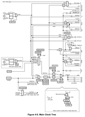
[3.] According to [TRM: Figure 4-5. Main Clock Tree]: the "mosc" clock signal is sourced by a multiplexer, the input of which is selected by the control signal "NOXTAL".
[4.] According to [TRM: Table 4-20. MOSCCTL Register Field Descriptions]: the PWRDN register bitfield... "provides user control over powering down the main oscillator circuit. This bit should be cleared when using a crystal and set for single-ended mode... 0x0 = Power to MOSC circuit is enabled. 0x1 = MOSC circuit is powered down."
[5.] According to [TRM: Table 4-20. MOSCCTL Register Field Descriptions]: the NOXTAL register bitfield... "provides the user control over the power drawn from the main
oscillator circuit. This bit should be set when either crystal or single-ended mode is being used. If the application needs MOSC, this bit should be cleared."
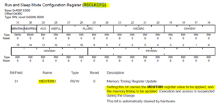
[6.] According to [TRM: Table 4-21. RSCLKCFG Register Field Descriptions]: the USEPLL register bitfield... "controls whether the clock source is specified by the OSCSRC field or the output of the PLL is provided to the system clock divider and serves as the system clock source. 0x0 = Clock source is specified by the OSCSRC field. 0x1 = Clock source is specified by the PLL."
[7.] According to [TRM: Table 4-21. RSCLKCFG Register Field Descriptions]: the OSCSRC register bitfield "specifies the oscillator source that becomes the oscillator clock (OSCCLK) source, which is used when the PLL is bypassed during run or sleep mode... 0x3 = MOSC is the oscillator source."
[8.] According to [Table 4-26. DSCLKCFG Register Field Descriptions]: the DSOSCSRC register bitfield "specifies the oscillator source that becomes the oscillator clock (OSCCLK) source, which is used when the PLL is bypassed during deep-sleep mode... 0x3 = MOSC"
Based on [1,2], it would appear that the MSP432E401Y can support an single-ended external clock reference with a frequency of 48 MHz.
Based on [0,3,4,5,6,7,8], it would appear that, ignoring the OSCCLK clock divider (which I expect is 1 by default), if I want to make SYSCLK a 48 MHz clock sourced by my single-ended external clock, I should:
[A.] Set MOSCCTL.PWRDN
[B.] Clear MOSCCTL.NOXTAL
[C.] Clear RSCLKCFG.USEPLL
[D.] Assign 0x3 to RSCLKCFG.DSOSCSRC
[E.] Assign 0x3 to RSCLKCFG.OSCSRC
Do you think this would work? If not, where might I look next for a solution?
Ultimately I can design a prototype board and test this with the actual external clock, but I'd like to exhaust all other options before doing so.
Thanks very much,
Dylan
Clock Tree, for reference: