This thread has been locked.

If you have a related question, please click the "Ask a related question" button in the top right corner. The newly created question will be automatically linked to this question.

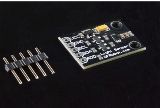
TM4C123GH6PM: I2C interface BH1750 reference code

Part Number: TM4C123GH6PM

Hi, 

Can you provide I2C interface reference code with BH1750 (light sensor).

Thanks & regards,

mounika.

#include <stdbool.h>
#include <stdint.h>
#include "inc/hw_i2c.h"
#include "inc/hw_memmap.h"
#include "inc/hw_types.h"
#include "driverlib/gpio.h"
#include "driverlib/i2c.h"
#include "driverlib/pin_map.h"
#include "driverlib/sysctl.h"
#include "driverlib/uart.h"
#include "utils/uartstdio.h"

#define BH1750_ADDRESS 0x23

void BH1750_Init(void);
void BH1750_Read(uint16_t *lightLevel);

void InitConsole(void)
{
    SysCtlPeripheralEnable(SYSCTL_PERIPH_GPIOB);

    GPIOPinConfigure(GPIO_PB0_U1RX);
    GPIOPinConfigure(GPIO_PB1_U1TX);

    SysCtlPeripheralEnable(SYSCTL_PERIPH_UART1);

    UARTClockSourceSet(UART1_BASE, UART_CLOCK_PIOSC);

    GPIOPinTypeUART(GPIO_PORTB_BASE, GPIO_PIN_0 | GPIO_PIN_1);

    UARTStdioConfig(1, 115200, 16000000);
}

int main(void)
{
    SysCtlClockSet(SYSCTL_SYSDIV_2_5 | SYSCTL_USE_PLL | SYSCTL_OSC_MAIN | SYSCTL_XTAL_16MHZ);
    InitConsole();
    BH1750_Init();

    while (1)
    {
        uint16_t lightLevel;
        BH1750_Read(&lightLevel);

        UARTprintf("Light Level: %d [lx]\n", lightLevel);

        SysCtlDelay(SysCtlClockGet() / 3); // Delay for a while before reading again.
    }
}

void BH1750_Init(void)
{
    SysCtlPeripheralEnable(SYSCTL_PERIPH_GPIOB);
    GPIOPinConfigure(GPIO_PB2_I2C0SCL);
    GPIOPinConfigure(GPIO_PB3_I2C0SDA);

    GPIOPinTypeI2CSCL(GPIO_PORTB_BASE, GPIO_PIN_2);
    GPIOPinTypeI2C(GPIO_PORTB_BASE, GPIO_PIN_3);

    SysCtlDelay(3);

    I2CMasterInitExpClk(I2C0_BASE, SysCtlClockGet(), true);
    I2CMasterSlaveAddrSet(I2C0_BASE, BH1750_ADDRESS, false);
}

void BH1750_Read(uint16_t *lightLevel)
{
    uint8_t data[2];

    // Send a command to start a measurement (e.g., continuous high-resolution mode)
    uint8_t command = 0x20; // Start measurement in continuous high-resolution mode

    I2CMasterControl(I2C0_BASE, I2C_MASTER_CMD_SINGLE_SEND);
    I2CMasterDataPut(I2C0_BASE, command);
    I2CMasterControl(I2C0_BASE, I2C_MASTER_CMD_SINGLE_SEND);
    while (I2CMasterBusy(I2C0_BASE))
    {
    }

    // Wait for the measurement to complete
    SysCtlDelay(SysCtlClockGet() / 10); // Wait for 100ms

    // Read 2 bytes of data
    I2CMasterControl(I2C0_BASE, I2C_MASTER_CMD_BURST_RECEIVE_START);
    while (I2CMasterBusy(I2C0_BASE))
    {
    }
    data[0] = I2CMasterDataGet(I2C0_BASE);

    I2CMasterControl(I2C0_BASE, I2C_MASTER_CMD_BURST_RECEIVE_FINISH);
    while (I2CMasterBusy(I2C0_BASE))
    {
    }
    data[1] = I2CMasterDataGet(I2C0_BASE);

    *lightLevel = (data[0] << 8) | data[1];
}
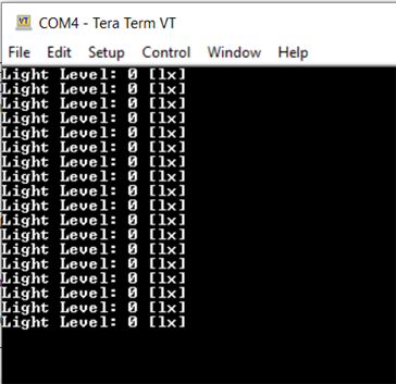
  • The above code is which I am running in ccs but while debugging my code is halting at bh1750 function call.

  • #include <stdbool.h>
    #include <stdint.h>
    #include "inc/hw_i2c.h"
    #include "inc/hw_memmap.h"
    #include "inc/hw_types.h"
    #include "driverlib/gpio.h"
    #include "driverlib/i2c.h"
    #include "driverlib/pin_map.h"
    #include "driverlib/sysctl.h"
    #include "driverlib/uart.h"
    #include "utils/uartstdio.h"
    
    #define BH1750_ADDRESS 0x23
    //#define BH1750_ADDRESS 0x5C
    
    void BH1750_Init(void);
    void BH1750_Read(uint16_t *lightLevel);
    
    void InitConsole(void)
    {
        // Enable GPIO port B for UART0 pins
        SysCtlPeripheralEnable(SYSCTL_PERIPH_GPIOB);
    
        // Configure UART0 pin muxing for port B pins 0 and 1
        GPIOPinConfigure(GPIO_PB0_U1RX);
        GPIOPinConfigure(GPIO_PB1_U1TX);
    
        // Enable UART0
        SysCtlPeripheralEnable(SYSCTL_PERIPH_UART1);
    
        // Use the internal 16MHz oscillator as the UART clock source
        UARTClockSourceSet(UART1_BASE, UART_CLOCK_PIOSC);
    
        // Select UART function for these pins
        GPIOPinTypeUART(GPIO_PORTB_BASE, GPIO_PIN_0 | GPIO_PIN_1);
    
        // Initialize UART0 for console I/O
        UARTStdioConfig(1, 115200, 16000000);
    }
    
    int main(void)
    {
        // Set the system clock to 80 MHz
        SysCtlClockSet(SYSCTL_SYSDIV_2_5 | SYSCTL_USE_PLL | SYSCTL_OSC_MAIN | SYSCTL_XTAL_16MHZ);
    
        // Initialize the UART for console output
        InitConsole();
    
        // Initialize the I2C communication and BH1750 sensor
        BH1750_Init();
    
        while (1)
        {
            uint16_t lightLevel;
            BH1750_Read(&lightLevel);
    
            // Display the light level via UART
            UARTprintf("Light Level: %d [lx]\n", lightLevel);
    
            // Delay for a while before reading again
            SysCtlDelay(SysCtlClockGet() / 3);
        }
    }
    
    void BH1750_Init(void)
    {
        // Enable GPIO port B for I2C0 pins
        SysCtlPeripheralEnable(SYSCTL_PERIPH_GPIOB);
        SysCtlPeripheralEnable(SYSCTL_PERIPH_I2C0);
        // Configure the pin muxing for I2C0 functions on port B pins 2 and 3
        GPIOPinConfigure(GPIO_PB2_I2C0SCL);
        GPIOPinConfigure(GPIO_PB3_I2C0SDA);
    
        // Set pin types for I2C communication
        GPIOPinTypeI2CSCL(GPIO_PORTB_BASE, GPIO_PIN_2);
        GPIOPinTypeI2C(GPIO_PORTB_BASE, GPIO_PIN_3);
    
        // Initialize the I2C peripheral
        I2CMasterInitExpClk(I2C0_BASE, SysCtlClockGet(), true);
    
        // Set the I2C slave address to BH1750_ADDRESS
        I2CMasterSlaveAddrSet(I2C0_BASE, BH1750_ADDRESS, false);
    }
    
    void BH1750_Read(uint16_t *lightLevel)
    {
        uint8_t data[2];
    
        // Send a command to start a measurement (e.g., continuous high-resolution mode)
        uint8_t command = 0x20; // Start measurement in continuous high-resolution mode
    
        // Send the command to the sensor
        I2CMasterControl(I2C0_BASE, I2C_MASTER_CMD_SINGLE_SEND);
        I2CMasterDataPut(I2C0_BASE, command);
        I2CMasterControl(I2C0_BASE, I2C_MASTER_CMD_SINGLE_SEND);
        while (I2CMasterBusy(I2C0_BASE))
        {
        }
    
        // Wait for the measurement to complete
        SysCtlDelay(SysCtlClockGet() / 100); // Wait for 10ms
    
        // Read 2 bytes of data from the sensor
        I2CMasterControl(I2C0_BASE, I2C_MASTER_CMD_BURST_RECEIVE_START);
        while (I2CMasterBusy(I2C0_BASE))
        {
        }
        data[0] = I2CMasterDataGet(I2C0_BASE);
    
        I2CMasterControl(I2C0_BASE, I2C_MASTER_CMD_BURST_RECEIVE_FINISH);
        while (I2CMasterBusy(I2C0_BASE))
        {
        }
        data[1] = I2CMasterDataGet(I2C0_BASE);
    
        // Combine the two bytes to get the light level
        *lightLevel = (data[0] << 8) | data[1];
    }
    

    updated code which iam using

  • There a few comments. 

    - Why do you have line 93? Are you trying to send a command to the slave device first? If that is the case, you just need line 94 and 95. You don't need line 93. When you execute line 93, you start a I2C bus transaction with no valid data in the I2C shift register. Therefore, you need to remove line 93. You first setup the data to be written in line 94 and then execute line 95 to start the I2C bus transaction. 

    - In line 104, you are trying to read from I2C slave. However, you didn't change the direction. You are still in the I2C write mode as in line 82. Before you read the data you need to first call     I2CMasterSlaveAddrSet(I2C0_BASE, BH1750_ADDRESS, true) to change the I2C to read mode. Without this, it won't work. 

    - Why don't you go through the example at C:\ti\TivaWare_C_Series-2.2.0.295\examples\boards\ek-tm4c123gxl-boostxl-senshub\humidity_sht21_simple on how to do I2C write and read to a simple SHT21 device. We don't have example for BH1750. Many of the I2C devices are similar in terms of read and write. You can reference this example. 

     - Here is a very useful I2C app note on how to use the various commands.https://www.ti.com/lit/pdf/spma073

     - I strongly suggest you use a logic analyzer or a scope to verify the waveform. It will alleviate much of your debugging time. 

  • i commented 93 line  and checked  but  I am still encountering the same issue.

    #include <stdbool.h>
    #include <stdint.h>
    #include "inc/hw_i2c.h"
    #include "inc/hw_memmap.h"
    #include "inc/hw_types.h"
    #include "driverlib/gpio.h"
    #include "driverlib/i2c.h"
    #include "driverlib/pin_map.h"
    #include "driverlib/sysctl.h"
    #include "driverlib/uart.h"
    #include "utils/uartstdio.h"
    
    #define BH1750_ADDRESS 0x23
    //#define BH1750_ADDRESS 0x5C
    
    void BH1750_Init(void);
    void BH1750_Read(uint16_t *lightLevel);
    
    void InitConsole(void)
    {
        // Enable GPIO port B for UART0 pins
        SysCtlPeripheralEnable(SYSCTL_PERIPH_GPIOB);
    
        // Configure UART0 pin muxing for port B pins 0 and 1
        GPIOPinConfigure(GPIO_PB0_U1RX);
        GPIOPinConfigure(GPIO_PB1_U1TX);
    
        // Enable UART0
        SysCtlPeripheralEnable(SYSCTL_PERIPH_UART1);
    
        // Use the internal 16MHz oscillator as the UART clock source
        UARTClockSourceSet(UART1_BASE, UART_CLOCK_PIOSC);
    
        // Select UART function for these pins
        GPIOPinTypeUART(GPIO_PORTB_BASE, GPIO_PIN_0 | GPIO_PIN_1);
    
        // Initialize UART0 for console I/O
        UARTStdioConfig(1, 115200, 16000000);
    }
    
    int main(void)
    {
        // Set the system clock to 80 MHz
        SysCtlClockSet(SYSCTL_SYSDIV_2_5 | SYSCTL_USE_PLL | SYSCTL_OSC_MAIN | SYSCTL_XTAL_16MHZ);
    
        // Initialize the UART for console output
        InitConsole();
    
        // Initialize the I2C communication and BH1750 sensor
        BH1750_Init();
    
        while (1)
        {
            uint16_t lightLevel;
            BH1750_Read(&lightLevel);
    
            // Display the light level via UART
            UARTprintf("Light Level: %d [lx]\n", lightLevel);
    
            // Delay for a while before reading again
            SysCtlDelay(SysCtlClockGet() / 3);
        }
    }
    
    void BH1750_Init(void)
    {
        // Enable GPIO port B for I2C0 pins
        SysCtlPeripheralEnable(SYSCTL_PERIPH_GPIOB);
        SysCtlPeripheralEnable(SYSCTL_PERIPH_I2C0);
        // Configure the pin muxing for I2C0 functions on port B pins 2 and 3
        GPIOPinConfigure(GPIO_PB2_I2C0SCL);
        GPIOPinConfigure(GPIO_PB3_I2C0SDA);
    
        // Set pin types for I2C communication
        GPIOPinTypeI2CSCL(GPIO_PORTB_BASE, GPIO_PIN_2);
        GPIOPinTypeI2C(GPIO_PORTB_BASE, GPIO_PIN_3);
    
        // Initialize the I2C peripheral
        I2CMasterInitExpClk(I2C0_BASE, SysCtlClockGet(), true);
    
        // Set the I2C slave address to BH1750_ADDRESS
        I2CMasterSlaveAddrSet(I2C0_BASE, BH1750_ADDRESS, false);
    }
    
    void BH1750_Read(uint16_t *lightLevel)
    {
        uint8_t data[2];
    
        // Send a command to start a measurement (e.g., continuous high-resolution mode)
        uint8_t command = 0x20; // Start measurement in continuous high-resolution mode
    
        // Send the command to the sensor
       // I2CMasterControl(I2C0_BASE, I2C_MASTER_CMD_SINGLE_SEND);
        I2CMasterDataPut(I2C0_BASE, command);
        I2CMasterControl(I2C0_BASE, I2C_MASTER_CMD_SINGLE_SEND);
        while (I2CMasterBusy(I2C0_BASE))
        {
        }
    
        // Wait for the measurement to complete
        SysCtlDelay(SysCtlClockGet() / 100); // Wait for 10ms
    
        // Read 2 bytes of data from the sensor
        I2CMasterControl(I2C0_BASE, I2C_MASTER_CMD_BURST_RECEIVE_START);
        while (I2CMasterBusy(I2C0_BASE))
        {
        }
        data[0] = I2CMasterDataGet(I2C0_BASE);
    
        I2CMasterControl(I2C0_BASE, I2C_MASTER_CMD_BURST_RECEIVE_FINISH);
        while (I2CMasterBusy(I2C0_BASE))
        {
        }
        data[1] = I2CMasterDataGet(I2C0_BASE);
    
        // Combine the two bytes to get the light level
        *lightLevel = (data[0] << 8) | data[1];
    }
    

  • Did you read my entire last reply?

    I said you had a problem with line 104 where you didn't change the master direction from write to read. You were in write mode to first a command to the slave. You need to change the direction to read in order to read. Please go through all my comments first before rejecting my answers so quickly.  

    - In line 104, you are trying to read from I2C slave. However, you didn't change the direction. You are still in the I2C write mode as in line 82. Before you read the data you need to first call     I2CMasterSlaveAddrSet(I2C0_BASE, BH1750_ADDRESS, true) to change the I2C to read mode. Without this, it won't work. 

    - Why don't you go through the example at C:\ti\TivaWare_C_Series-2.2.0.295\examples\boards\ek-tm4c123gxl-boostxl-senshub\humidity_sht21_simple on how to do I2C write and read to a simple SHT21 device. We don't have example for BH1750. Many of the I2C devices are similar in terms of read and write. You can reference this example. 

     - Here is a very useful I2C app note on how to use the various commands.https://www.ti.com/lit/pdf/spma073

     - I strongly suggest you use a logic analyzer or a scope to verify the waveform. It will alleviate much of your debugging time. 

  • Hi,

     Do you have any update? Is your problem resolved?

  • Hi,

      I have not heard back from you. I will close the thread for now. If you have any update, you can write back to this post and the thread will automatically change the status to Open again.