This thread has been locked.

If you have a related question, please click the "Ask a related question" button in the top right corner. The newly created question will be automatically linked to this question.

EK-TM4C123GXL: SSI via uDMA got why the interrupt fires twice?

Part Number: EK-TM4C123GXL

I use SSI with uDMA.

When the primary channel is finished there is one interrupt, when the alternativly channel is finished there are 2 interrupts.

At this time no primary channel is started anymore.
Why is it like this?

My Hardware Config:

void init_SSI0_TO_GPIO_PA5()
{
    // enable SSI1 Tx PA5 only
    
    MAP_SysCtlPeripheralEnable(SYSCTL_PERIPH_SSI0);
    while(!MAP_SysCtlPeripheralReady(SYSCTL_PERIPH_SSI0));
    
    // port config
    MAP_GPIOPinConfigure(GPIO_PA5_SSI0TX);
    MAP_GPIOPinTypeSSI(GPIO_PORTA_BASE, GPIO_PIN_5);
    
    MAP_GPIOPadConfigSet(GPIO_PORTA_BASE, GPIO_PIN_5, 
                         GPIO_STRENGTH_2MA, GPIO_PIN_TYPE_STD);
    
    // SSI config
    MAP_IntDisable(INT_SSI0);
    MAP_SSIIntDisable(SSI0_BASE, SSI_TXFF | SSI_RXFF | SSI_RXTO | SSI_RXOR);
    MAP_SSIDisable(SSI0_BASE);
    MAP_SSIConfigSetExpClk(SSI0_BASE, SysCtlClockGet(), SSI_FRF_MOTO_MODE_1, 
                           SSI_MODE_MASTER, SSI_CLOCK, 8);
    
    // ------------------ //
    // Priority Levels
    // Priority 4 = 0xE0 ->lower
    // Priority 3 = 0x60
    // Priority 2 = 0x20
    // Priority 1 = 0x00 ->higher
    // ------------------ //
    
    MAP_IntPrioritySet(INT_SSI0, 0x00); // Priority 1 !!!
    MAP_IntEnable(INT_SSI0);
    MAP_SSIEnable(SSI0_BASE);
}

void init_uDMA()
{
    MAP_SysCtlPeripheralEnable(SYSCTL_PERIPH_UDMA);
    while(!MAP_SysCtlPeripheralReady(SYSCTL_PERIPH_UDMA));
    
    // general uDMA setup
    MAP_uDMAEnable();
    MAP_SysCtlDelay(10);
    
    // declare controltable
    MAP_uDMAControlBaseSet(uDMAControlTable);
    MAP_SysCtlDelay(10);
    
    MAP_IntEnable(INT_UDMAERR);
    
    init_uDMA_CH11_SSI0();
    init_uDMA_CH25_SSI1();
    init_uDMA_CH13_SSI2();
    init_uDMA_CH15_SSI3();
    init_uDMA_CH6_CH7_UART5();
}

void init_uDMA_CH11_SSI0()
{
    // uDMA Channel 11 enc 0
    MAP_SSIDMADisable(SSI0_BASE, SSI_DMA_RX | SSI_DMA_TX);
    
    MAP_uDMAChannelAssign(UDMA_CH11_SSI0TX);
    MAP_uDMAChannelAttributeDisable(11, 
                                    UDMA_ATTR_ALTSELECT | 
                                    UDMA_ATTR_HIGH_PRIORITY | 
                                    UDMA_ATTR_REQMASK | 
                                    UDMA_ATTR_USEBURST);
    
    MAP_uDMAChannelControlSet(11 | UDMA_PRI_SELECT, 
                              UDMA_SIZE_8 | UDMA_SRC_INC_8 | 
                              UDMA_DST_INC_NONE | UDMA_ARB_4);
    
    MAP_uDMAChannelControlSet(11 | UDMA_ALT_SELECT, 
                              UDMA_SIZE_8 | UDMA_SRC_INC_8 | 
                              UDMA_DST_INC_NONE | UDMA_ARB_4);
    
    MAP_uDMAChannelAttributeEnable(11, UDMA_ATTR_USEBURST | UDMA_ATTR_HIGH_PRIORITY);
    MAP_SSIDMAEnable(SSI0_BASE, SSI_DMA_TX);
    MAP_SSIEnable(SSI0_BASE);
}

void uDMASSI0IntHandler(void)
{
#ifdef DEBUG_GPIO
    DEBUG_PA7 = GPIO_PIN_7; // CH05 INTLED0
#endif
    
    MAP_SSIIntClear(SSI0_BASE, SSI_RXTO | SSI_RXOR);
    MAP_uDMAIntClear(11);
    
    if (MAP_uDMAChannelModeGet(11 | UDMA_PRI_SELECT) == UDMA_MODE_STOP)
    {
        uDMABufferStateSSI0_PRI = EMPTY;
    }
    
    if (MAP_uDMAChannelModeGet(11 | UDMA_ALT_SELECT) == UDMA_MODE_STOP)
    {
        uDMABufferStateSSI0_ALT = EMPTY;
    }
    
#ifdef DEBUG_GPIO
    DEBUG_PA7 = 0; // CH05 INTLED0
#endif
}

void start_uDMA_SSI0()
{
    MAP_uDMAChannelTransferSet(11 | UDMA_PRI_SELECT, 
                               UDMA_MODE_PINGPONG, &uDMABufferSSI0_PRI, 
                               (void *)(SSI0_BASE + SSI_O_DR), 
                               SSI_TRANSFERSIZE);
    
    MAP_uDMAChannelEnable(11 | UDMA_PRI_SELECT);
    uDMABufferStateSSI0_PRI = EMPTYING;
    uDMABufferModeSSI0 = PONG;
    
    MAP_uDMAChannelTransferSet(11 | UDMA_ALT_SELECT, 
                               UDMA_MODE_PINGPONG, &uDMABufferSSI0_ALT, 
                               (void *)(SSI0_BASE + SSI_O_DR), 
                               SSI_TRANSFERSIZE);
    
    MAP_uDMAChannelEnable(11 | UDMA_ALT_SELECT);
    uDMABufferStateSSI0_ALT = EMPTYING;
    uDMABufferModeSSI0 = PING;
}

  • Hi,

      I don't know the reason to your problem but I have some comments/questions.

      - I'm not clear with your init_SSI0_TO_GPIO_PA5 function. You seem to only configure TX pin but not the SPICLK pin. How can SPI work without the clock. This is independent of the uDMA problem you are reporting. Perhaps I'm not understanding your application.

      - How fast is SSI_CLOCK? 

      - Why would you need ping-pong mode for TX transfer? Normally, ping-pong mode is used for RX because the processor would need to process the data while more data are coming in in an asynchronous fashion. For TX, I think it would be better with Basic mode. If you refer to the udma_demo example, UARTTX is setup for Basic mode only while the UARTRX is setup for ping-pong. 

      - What is the SSI_TRANSFERSIZE? You can increase it to 2x or even more with Basic mode configuration rather using Pri/Alt in ping-pong mode. My point is that there is not really performance benefit to use ping-pong mode for TX. 

  • I have changed the code slightly to better explain my problem.
    First I want to explain the SSI configuration. I used the SSI periphery to create a simple PWM data signal, so no SSI data signal. This I had solved first very complex with timers. But now I found out that this works even better and much more efficient with the SSI periphery. It seems that the additional interrupt comes from the Rx. But why?
    I don't have to receive anything via Rx and therefore I didn't configure Rx. What can I do to disable this third interrupt? I don't need it and it costs me unnecessary time.I have already tried several combinations with the function SSIIntDisable(). None of them worked.

    EDIT: In this picture a uDMA PRI channel was started and a uDMA ALT channel. But when the PRI channel was finished, no new PRI channel was started. This is also intentional. How can I stop a uDMA PING PONG mode correctly? Without that an additional interrupt comes?

    EDIT2: The third interrupt comes from the udmaerror. When i comment it out this line: MAP_IntEnable(INT_UDMAERR);
    Then the third interrupt is gone. But why? I use for the udmaerror an another isr and this isr is declared in the __startupfile.

    EDIT:3 I have disabled all interrupts and enabled only the one. So that I can find the error more easily. So I am quite confused!!! I have now changed several times 2 things and get this additional interrupt again or not.
    1. line is active MAP_IntEnable(INT_UDMAERR);
    and in the SSI0 ISR is my additional debug code not in it. The isr is about 1.4us active. The third interrupt is there.
    2. line is active MAP_IntEnable(INT_UDMAERR);
    and SSI0 ISR has my additional debug code in it. The isr is about 2.7us active. The third interrupt is not there.
    3. line is not active MAP_IntEnable(INT_UDMAERR);
    and SSI0 ISR has my additional debug code in it. The isr is about 2.7us active. The third interrupt is there.
    Can someone please explain this to me? otherwise I have to get gasoline and burn this all down :D

    EDIT4: It looks like the third interrupt is the "TX FIFO half full or less" although it is disabled. If I understand this correctly. All peripheral interrupts must be disabled before the periphery is linked to uDMA. So that uDMA can send a ready pulse via the ISR to the respective peripheral. It looks like when the udma alt channel sends a done pulse to the isr, and the isr handles it quickly. shortly after that comes another pulse from the peripheral(SSI0) Could this be an architecture problem?

    #define SSI_TRANSFERSIZE (12)
    #define SSI_CLOCK (4800000)
    
    void init_SSI0_TO_GPIO_PA5()
    {
        // enable SSI1 Tx PA5 only
        
        MAP_SysCtlPeripheralEnable(SYSCTL_PERIPH_SSI0);
        while(!MAP_SysCtlPeripheralReady(SYSCTL_PERIPH_SSI0));
        
        // port config Tx
        MAP_GPIOPinConfigure(GPIO_PA5_SSI0TX);
        MAP_GPIOPinTypeSSI(GPIO_PORTA_BASE, GPIO_PIN_5);
        
        MAP_GPIOPadConfigSet(GPIO_PORTA_BASE, GPIO_PIN_5, 
                             GPIO_STRENGTH_2MA, GPIO_PIN_TYPE_STD);
        // SSI config
        MAP_IntDisable(INT_SSI0);
        MAP_SSIIntDisable(SSI0_BASE, SSI_TXFF | SSI_RXFF | SSI_RXTO | SSI_RXOR);
        MAP_SSIDisable(SSI0_BASE);
        MAP_SSIConfigSetExpClk(SSI0_BASE, SysCtlClockGet(), SSI_FRF_MOTO_MODE_1, 
                               SSI_MODE_MASTER, SSI_CLOCK, 8);
        
        // ------------------ //
        // Priority Levels
        // Priority 4 = 0xE0 ->lower
        // Priority 3 = 0x60
        // Priority 2 = 0x20
        // Priority 1 = 0x00 ->higher
        // ------------------ //
        
        MAP_IntPrioritySet(INT_SSI0, 0x00); // Priority 1 !!!
        MAP_IntEnable(INT_SSI0);
    }
    
    void init_uDMA_CH11_SSI0()
    {
        // uDMA Channel 11 enc 0
        MAP_SSIDMADisable(SSI0_BASE, SSI_DMA_RX | SSI_DMA_TX);
        
        MAP_uDMAChannelAssign(UDMA_CH11_SSI0TX);
        MAP_uDMAChannelAttributeDisable(11, 
                                        UDMA_ATTR_ALTSELECT | 
                                        UDMA_ATTR_HIGH_PRIORITY | 
                                        UDMA_ATTR_REQMASK | 
                                        UDMA_ATTR_USEBURST);
        
        MAP_uDMAChannelControlSet(11 | UDMA_PRI_SELECT, 
                                  UDMA_SIZE_8 | UDMA_SRC_INC_8 | 
                                  UDMA_DST_INC_NONE | UDMA_ARB_4);
        
        MAP_uDMAChannelControlSet(11 | UDMA_ALT_SELECT, 
                                  UDMA_SIZE_8 | UDMA_SRC_INC_8 | 
                                  UDMA_DST_INC_NONE | UDMA_ARB_4);
        
        MAP_uDMAChannelAttributeEnable(11, UDMA_ATTR_USEBURST);
        MAP_SSIDMAEnable(SSI0_BASE, SSI_DMA_TX);
        MAP_SSIEnable(SSI0_BASE);
    }
    
    void start_uDMA_SSI0_PRI(uint8_t* buffer)
    {
    #ifdef DEBUG_GPIO
        DEBUG_PA6 = GPIO_PIN_6; // CH04 SSI0 PRI
    #endif
        
        MAP_uDMAChannelTransferSet(11 | UDMA_PRI_SELECT, 
                                   UDMA_MODE_PINGPONG, buffer, 
                                   (void *)(SSI0_BASE + SSI_O_DR), 
                                   SSI_TRANSFERSIZE);
        
        MAP_uDMAChannelEnable(11 | UDMA_PRI_SELECT);
        SSI0_bufMode = BUF_PONG;
        SSI0_PRI_bufState = BUF_EMPTYING;
    }
    
    void start_uDMA_SSI0_ALT(uint8_t* buffer)
    {
    #ifdef DEBUG_GPIO
        DEBUG_PA7 = GPIO_PIN_7; // CH05 SSI0 ALT
    #endif
        MAP_uDMAChannelTransferSet(11 | UDMA_ALT_SELECT, 
                                   UDMA_MODE_PINGPONG, buffer, 
                                   (void *)(SSI0_BASE + SSI_O_DR), 
                                   SSI_TRANSFERSIZE);
        
        MAP_uDMAChannelEnable(11 | UDMA_ALT_SELECT);
        SSI0_bufMode = BUF_PING;
        SSI0_ALT_bufState = BUF_EMPTYING;
    }
    
    void uDMASSI0IntHandler(void)
    {
    #ifdef DEBUG_GPIO
        DEBUG_PA3 = GPIO_PIN_3; // CH02 SSI0 INT
    #endif
        if (intCounter == 0)
        {
            intStatusDMA0 = uDMAIntStatus();
            intStatusRaw0 = SSIIntStatus(SSI0_BASE, 0);
            intStatusMask0 = SSIIntStatus(SSI0_BASE, 1);
        }
        if (intCounter == 1)
        {
            intStatusDMA1 = uDMAIntStatus();
            intStatusRaw1 = SSIIntStatus(SSI0_BASE, 0);
            intStatusMask1 = SSIIntStatus(SSI0_BASE, 1);
        }
        if (intCounter == 2)
        {
            intStatusDMA2 = uDMAIntStatus();
            intStatusRaw2 = SSIIntStatus(SSI0_BASE, 0);
            intStatusMask2 = SSIIntStatus(SSI0_BASE, 1);
        }
        if (intCounter == 3)
        {
            intCounter = 0;
        }
        intCounter++;
        
        MAP_SSIIntClear(SSI0_BASE, SSI_RXFF | SSI_RXOR);
        MAP_uDMAIntClear(11);
        if (MAP_uDMAChannelModeGet(11 | UDMA_PRI_SELECT) == UDMA_MODE_STOP)
        {
    #ifdef DEBUG_GPIO
            DEBUG_PA6 = 0; // CH04 SSI0 PRI
    #endif
            SSI0_PRI_bufState = BUF_EMPTY;
        }
        if (MAP_uDMAChannelModeGet(11 | UDMA_ALT_SELECT) == UDMA_MODE_STOP)
        {
    #ifdef DEBUG_GPIO
            DEBUG_PA7 = 0; // CH05 SSI0 ALT
    #endif
            SSI0_ALT_bufState = BUF_EMPTY;
        }
    #ifdef DEBUG_GPIO
        DEBUG_PA3 = 0; // CH02 SSI0 INT
    #endif
    }

  • EDIT2: The third interrupt comes from the udmaerror. When i comment it out this line: MAP_IntEnable(INT_UDMAERR);

    If you get a UDMAERR it means you are getting a bus error. uDMA is another bus master on the bus. Normally, when a bus master tries to access an address that is unimplemented, a bus error can be generated. I suppose the only uDMA channel you have set up is the SSI0TX, correct? If you have other uDMA channels running, I will suggest you disable all other channels and focus on SSI0TX channel to see if the udmaerr is related to SSI0TX transfer. 

    You didn't configure the RX pin (from the pinmux point of view) to receive data on the pin but that does not mean the shift register is not receiving some garbage. The SSI is full-duplex. When the SPICLK is clocking, the shift register is also clocking in data. It is just not taking data from the physical pin. Since you didn't enable the RX interrupt on the SSIIM register, whatever is clocked in is immaterial as you don't care what is received on the shift register. 

  • Yes I have only activated the SSI0 Tx. Yes all other channels and interrupts are not active to further isolate the error. Is there an udma error if no other channel is started in pingpong mode? How can I exit ping pong mode correctly?

  • Normally after all data is transferred, the channel is supposed to stop by itself. If you poll the channel status using MAP_uDMAChannelModeGet it should return UDMA_MODE_STOP. I'm still not clear with your third interrupt if it is due to uDMAERR or due to completion of the ALT packet. 

    I guess I asked you before if you see the same phenomenon if you configure for BASIC mode instead of the PING-PONG mode.  

  • I guess I asked you before if you see the same phenomenon if you configure for BASIC mode instead of the PING-PONG mode.

    I got only one Interrupt, when i configure dma in basic mode. And i make a breakpoint in the udma error isr and no interrupt is comming there. i also have ther an udma error counter. and the counter still on zero.

    but this is not a solution for me, because i need an uninterrupted signal. here i only show how i drive 2 pixels, i reduced the number of pixels to find the error easier. i need much more pixels and i want to try to process them in real time now. by this i mean, instead of preparing the pixel data of all pixels and then sending them in a long dma e.g. 600 items or more.

  • Understand your desire to use ping-pong mode. I just wanted to isolate the problem if it is due to ping-pong mode or even basic mode will create an extra interrupt. At the moment, I don't know what caused the UDMAERR. As I mentioned, it is an error due to uDMA accessing an address that is unimplemented or protected. I will suggest in ping-pong mode, start with a small transfer size and see if you are getting the unwanted interrupt. Gradually increase the transfer size and see if the problem persists. Also play with the arbitration size. I wonder if it makes a difference. 

    If the μDMA controller encounters a bus or memory protection error as it attempts to perform a data
    transfer, it disables the μDMA channel that caused the error and generates an interrupt on the μDMA
    error interrupt vector. The processor can read the DMA Bus Error Clear (DMAERRCLR) register
    to determine if an error is pending. The ERRCLR bit is set if an error occurred. The error can be
    cleared by writing a 1 to the ERRCLR bit.

  • I have now tested various combinations. The additional interrupt only occurs in Ping Pong mode. The additional interrupt comes only if no new PRI or ALT channel is started. The uDMAError isr has never triggered. In the uDMAError is as you recommended the function call to clear the interrupt bit. I am of the opinion it has nothing to do with a uDMAError. If I start a uDMA channel 10 times or 20 times to keep the ping pong mode alive, no extra interrupt comes. Only when I don't start a PRI or ALT channel again. Is there anything else I can test or check?

    Another theory. If I look closely at the time axis with my logic analyzer. Could the extra interrupt be a Tx FiFo Half Full or Less interrupt.

  • The additional interrupt comes only if no new PRI or ALT channel is started. The uDMAError isr has never triggered.

    You said the uDMA ISR is never triggered but you also said you are getting an uDMAError. This is where I'm confused. 

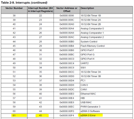
    I want to make sure one thing so we are on the same page. If you put a breakpoint on your uDMAError handler for interrupt number 45, do you halt at the ISR? If not, why do you say you are seeing a third interrupt that is due to uDMAError? If you think the third interrupt is due to Tx FIFO full or less then you will not see a uDMAError. The SSI0 interrupt is at interrupt number 7. Is your third interrupt trapped in the ISR handler for the interrupt number 7?

  • I just see that the translation is very bad in EDIT2. Sorry for the confusion. I do not have uDMAError. And the ISR for uDMA is not called either.


    The SSI0 ISR is called correctly by a uDMA Pri done or uDMA Alt done. But if no new PRI or ALT uDMA channel is started an additional interrupt comes after.

    I used from the Tiva ware the example project with IAR. There I have assigned in the startup file all isr correctly to a function.

  • The SSI0 ISR is called correctly by a uDMA Pri done or uDMA Alt done. But if no new PRI or ALT uDMA channel is started an additional interrupt comes after.

    That makes more sense now. Earlier for several posts, you have been talking about uDMAError and the effect of calling MAP_IntEnable(INT_UDMAERR).

    In that case, I agree with you that the third interrupt is due to the FIFO TX is less than half full of less. In the ISR, why don't you try to disable the interrupt (SSI_TXFF) after you complete the transfer when the ALT channel status becomes UDMA_MODE_STOP. 

    Another thing is can you try with uDMA arbitration size equal to 2 or 1 as in UDMA_ARB_2 or UDMA_ARB_1. I'd like to know if that makes a difference. 

  • I have already tried to disable this interrupt with:
    MAP_SSIIntDisable(SSI0_BASE, SSI_TXFF | SSI_RXFF | SSI_RXTO | SSI_RXOR);
    But this has no effect. I disabled these interrupts directly in my hardware configuration. Does it make a difference if this instruction is executed in the ISR?

    I have tested with UDMA_ARB_1 and UDMA_ARB_2. No change. Except that the first time I start the PRI channel it takes a little longer to finish.

  • HI,

     What if you disable the interrupt earlier when the PRI reaches UDMA_MODE_STOP instead of waiting for ALT to complete. Does that make a difference?

      I want to also give you a heads-up. I will be on vacation starting tomorrow for a week. Please expect delay in my response. 

  • It doesn’t make a difference when I clear or deactivate the interrupts. I have tried many variants. Additionally, the interrupts are masked, and no unmasked interrupt occurs.

    I have now looked into the topic in detail. The SSI peripheral can apparently send both a single request and a burst request to uDMA. It depends on how many items still need to be sent and how the Arbitration Size is set. This makes sense in order to complete the transfer. The FIFO has a memory of 8 x 16-bit. The burst request is fixed at 4 due to the SSI TX Half Full or Less Interrupt. To carry out an efficient uDMA transfer, it makes sense to set the Arbitration Size to 4. This way, when an SSI TX Half Full or Less Interrupt occurs, uDMA transfers 4 items in a burst. The Item Size was set to 6. The combination of an Item Size of 6 and an Arbitration Size of 4 is not efficient. So, I increased the Item Size to 12 so that 3 x 4 items can be transferred per burst request.

    Then, I experimented with the command to set “use burst.”
    Is it correct that it has no impact on the request?
    I observed that the first transfer, i.e., when the TX FIFO is completely empty, is always a burst. But what about the remaining items? Do they get an SSI TX Not Full interrupt, and does DMA make a single request?

    I also found out that I must execute the “use burst” command every time before a uDMA channel is started because the bit is cleared after the channel starts.

    Do I have to set the “use burst” bit every time to ensure that the entire transfer always sends a burst request, or do I have no influence on that?

    I have no direct influence on whether the additional interrupt occurs or not. Adding a few instructions to the code is enough for the interrupt to either appear or disappear. It is an unsolvable timing problem. When the uDMA channel is finished and no new one was started in Ping Pong mode, and the interrupt from the SSI occurs, then the SSI ISR is called again. In my eyes, this is a design flaw, as all SSI interrupts are deactivated.

  • Hi Kevin,

      I'm currently on vacation. I will look into your question when I come back. Sorry for the delayed response.