This thread has been locked.

If you have a related question, please click the "Ask a related question" button in the top right corner. The newly created question will be automatically linked to this question.

LP-MSPM0L1306: About GPIO interrupts

Part Number: LP-MSPM0L1306

When an input pin set as GPIO is detected, a function program called "GROUP1_IRQHandler" will be executed if interrupt settings are made.
If I want to specify different interrupt destinations (other than GROUP1_IRQHandler) for PA14 and PA18, what kind of settings should I use and what kind of code should I write?

The specific content is
- If PA14 is input, execute "GROUP1_IRQHandler"
- If PA18 is input, I want to set and execute a program that is a different interrupt destination than "GROUP1_IRQHandler".
In conclusion, I would like to separate the interrupt destination programs between PA14 and PA18.

  • Hi Ryota,

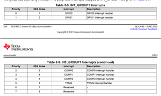
    We combo all GPIO, COMP and TRING interrupt into GROUP1:

    Thus you need to follow the below step to separate PA14 or PA18 GPIO interrupt:

    Step 1: Check if this intrrupt sourcing from GPIO (GROUP IIDX)

    Step 2: Check  GPIO IIDX

    Example:

    void GROUP1_IRQHandler(void)
    {
        /*
         * Get the pending interrupt for the GPIOA port and store for
         * comparisons later
         */
        uint32_t gpioA = DL_GPIO_getEnabledInterruptStatus(GPIOA,
            GPIO_SWITCHES_USER_SWITCH_1_PIN | GPIO_SWITCHES_USER_SWITCH_3_PIN);
    
        /*
         * Bitwise AND the pending interrupt with the pin you want to check,
         * then check if it is equal to the pins. Clear the interrupt status.
         */
        if ((gpioA & GPIO_SWITCHES_USER_SWITCH_1_PIN) ==
            GPIO_SWITCHES_USER_SWITCH_1_PIN) {
            DL_GPIO_togglePins(
                GPIO_LEDS_USER_LED_1_PORT, GPIO_LEDS_USER_LED_1_PIN);
            DL_GPIO_clearInterruptStatus(GPIOA, GPIO_SWITCHES_USER_SWITCH_1_PIN);
        }
    
        if ((gpioA & GPIO_SWITCHES_USER_SWITCH_3_PIN) ==
            GPIO_SWITCHES_USER_SWITCH_3_PIN) {
            DL_GPIO_togglePins(
                GPIO_LEDS_USER_LED_3_PORT, GPIO_LEDS_USER_LED_3_PIN);
            DL_GPIO_clearInterruptStatus(GPIOA, GPIO_SWITCHES_USER_SWITCH_3_PIN);
        }
    
        /* Repeat with GPIOB Port */
        uint32_t gpioB = DL_GPIO_getEnabledInterruptStatus(
            GPIOB, GPIO_SWITCHES_USER_SWITCH_2_PIN);
    
        if ((gpioB & GPIO_SWITCHES_USER_SWITCH_2_PIN) ==
            GPIO_SWITCHES_USER_SWITCH_2_PIN) {
            DL_GPIO_togglePins(
                GPIO_LEDS_USER_LED_2_PORT, GPIO_LEDS_USER_LED_2_PIN);
            DL_GPIO_clearInterruptStatus(GPIOB, GPIO_SWITCHES_USER_SWITCH_2_PIN);
        }
    }

    In this examlpe, we just enable two GPIO interrupt, thus we don't run Step 1 to same some time here.

    You can find this examlpe code in our SDK:

    Thanks!

    Best Regards

    Johnson

  • It worked fine.
    thank you.

    However, since I do not fully understand the contents of the program, I would like to ask you to specifically explain the following parts.

    if ((gpioA & GPIO_SWITCHES_USER_SWITCH_1_PIN) ==
    GPIO_SWITCHES_USER_SWITCH_1_PIN)

    I don't really understand this part.

    Why when detecting an input signal
    Will (gpioA & GPIO_SWITCHES_USER_SWITCH_1_PIN) and (GPIO_SWITCHES_USER_SWITCH_1_PIN) be equal?
    What kind of movements and changes in values ​​are occurring in the system?
  • Hi Ryota,

    No, GPIOA should run read gpio status code, GPIO_SWITCHES_USER_SWITCH_1_PIN should a pre-define.

    You can try to see the low level code and RTM to understand this logic.

    Thanks!

    Best Regards

    Johnson

  • The comment is pretty clear:

    /*
         * Bitwise AND the pending interrupt with the pin you want to check,
         * then check if it is equal to the pins. Clear the interrupt status.
         */

    gpioa is a combination of all the pins that may have caused the interrupt, so you need to check each individual bit.

  • Please let me know if there is any difference in understanding.
    For example
    GPIO PA0 to PA7 exist
    When monitoring this bit by bit,
    0bit: PA0, 1bit: PA1, ~7bit: PA7
    GPIO_SWITCHES_USER_SWITCH_0_PIN = PA0GPIO_SWITCHES_USER_SWITCH_1_PIN =
    If GPIO_SWITCHES_USER_SWITCH_1_PIN = PA1,
    Assuming that PA0 is input, and replacing the contents of the code below with bits (gpioA gets GPIO's pending interrupt)
    ・if ((gpioA & GPIO_SWITCHES_USER_SWITCH_1_PIN)
    == GPIO_SWITCHES_USER_SWITCH_1_PIN)
    →00000001 & 00000001 = 00000001
    →This is executed because it is true.
    After that, if PA1 is input while PA0 continues to detect input, (assuming that DL_GPIO_clearInterruptStatus(GPIOA, GPIO_SWITCHES_USER_SWITCH_0_PIN) is executed in the if statement)
    →00000010 & 00000001 = 00000001
    →This is false and will not be executed.
    Am I correct in my understanding that this is how it works?

  • Hi Ryota,

    Yes, correct.

    Thanks!

    Best Regards

    Johnson