This thread has been locked.

If you have a related question, please click the "Ask a related question" button in the top right corner. The newly created question will be automatically linked to this question.

TM4C129XNCZAD: Internal Ethernet of TI_MCU on PCB does not work

Part Number: TM4C129XNCZAD
Other Parts Discussed in Thread: EK-TM4C1294XL, EK-TM4C129EXL, TLK110, UNIFLASH

Dear All,

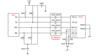
I embbedded the TM4C129XNCZAD on PCB.

The board is supposed to connect though ethernet port but I can not get any to get signal on the EN0TXP/N pin.

I read the related thread and I realized that the voltage on RBIAS on my board is not 1.2V.  it is rather 0V.

According to information on the forum, In the mentioned condintion the MCU can not properly work.

I checked the VDD pins and VDDC pins, they have adequate voltage.

Could anyone know what may cause RBIAS to have 0V?

Kind regards,

Jean 

  • Hi,

      Can you show your schematic for the Ethernet interface? Do you have the correct transformer and protection diode? Can you go through the TM4C129 System Design Guideline for recommendation on the Ethernet interface?  https://www.ti.com/lit/pdf/spma056

  • Hi Charles,

    Yes, I did design according to recommended design in TI documentations.

    However, I am tesing the MCU ethernet before I finish soldering of the magnetics.

    Could this be the reason why there is no signal coming out or voltage on RBIAS turn to be 1.2 V?

    Kind regards,

    Jean

  • Dear Charles,

    Thank you for the suggestion.

    I tried to terminate the connections on the ethernet EN0TXP/Nwith magnet as suggested but the issue was not resolved.

    However, when you erase the MCU flash with XDS110 debugger, the voltage on RBIAS incresead to about 1 volt .

    Is there anyway, the voltage at RBIAS may also depend on the firmware or configurations in firmware?

    If so, what function or settings should be adjusted?

    Kind regards,

    Jean

  • Hi Jean,

      Can you please answer me some basic questions? I want to know if you are having some issue running a Ethernet application that leads you to think that the problem may be related to your RBIAS voltage. Or you just build your board and wonder what should be the correct RBIAS voltage for different circumstances. 

    - Can you get the Ethernet to work by running a Ethernet example on your custom board? For example, run the C:\ti\TivaWare_C_Series-2.2.0.295\examples\boards\ek-tm4c1294xl\enet_lwip. Does it work on your custom board. 

    - Can you get the Ethernet to work by running a Ethernet example on a LaunchPad?

    - What is the RBIAS voltage you measure on the LaunchPad?

    - Do you have other customer boards or you only have one?

    - If you have multiple boards, do you measure consistently the same voltage on the RBIAS pins?

    - How does the RBIAS voltage compared between the LaunchPad and your custom boards?

    - How is your Ethernet interface connections compared to Figure 24-15? See below

    I must say I don't know what should be the expected RBIAS voltage at different operation conditions (e.g. power up, during Ethernet idle, during transmit/receive an etc) because this is not really specified on the datasheet. RBIAS pin must be connected to GND through a 4.87kohm resistor. This is all that is specified and needed.  If you follow the System Design Guideline and the datasheet recommended connections for the Ethernet PHY interface then the Ethernet should work. Please see below again. Do you have your schematic matching as much as possible to the below figure. Because at the end, if your Ethernet operation is not working, it may be due to the rest of Ethernet circuitry, not the RBIAS if you have already connected to GND through a recommended resistor. 

    I don't know if you tried to test your Ethernet operation in the past without the protection diode and magnet. If you simply just connect to a RJ45 directly, you may have damaged the device. 

  • Hi Charles,

    Thank you for the reply.

    The goal is to run an ethernet application on the mentioned PCB.

    Here is what I have teried so far;

    For feasibility study I used EK-TM4C129EXL as It is harder to get the DK_TM4C129X.(DK_TM4C129X could have been ideal as PCB uses TM4C129XNCZAD IC)

    That means programs runs properly on the EK-TM4C129EXL launch pad.

    Then I tried to modify pograms and run them on the PCB with TM4C129XNCZAD (by changing target and pinouts ) .

    The programs failed to connect the ethernet. ( forexample example ene-io).

    I had to check on TI forum whether no other people had same issue and it is where I realized that voltage on RBIAS needs to be around 1.2 V to get the ethernet working correctly.

    Then, I checked my PCB and found that the RBIAS was zero, suspected that should be the main reason...

    I even even tried TI original example C:\ti\TivaWare_C_Series-2.2.0.295\examples\boards\dk-tm4c1294xl\enet_io aimed for TM4C129XNCZAD but it failed

    I then erased the flash to get MCU back on factory setting. Suprisingly, that did get the voltage on RBIAS around 1V and the ethernet did work.

    So I kind think that i need to figure out the best way to initialize the ethernet.

    I also read in the errata for silicon revision 1,2 and 3 published by TI, It was mentioned that it sometimes Ethernet may initialize but may not start properly and setting in FLASHCONF.FPOFF maybe needed... 

    Does this apply to TM4C129XNCZAD as well? 

    The other question is how does Erase flash program initialize the ethernet?

    By the way, The design is similar to TLK110 transformerless connection.

    Kind regards,

    Jean

  • The programs failed to connect the ethernet. ( forexample example ene-io).

    I had to check on TI forum whether no other people had same issue and it is where I realized that voltage on RBIAS needs to be around 1.2 V to get the ethernet working correctly.

    Hi,

      I suppose you are running an example such as enet_io on EK-TM4C129EXL LaunchPad, correct. Yes, the example is expected to run out of box without modification.

    The programs failed to connect the ethernet. ( forexample example ene-io).

    I had to check on TI forum whether no other people had same issue and it is where I realized that voltage on RBIAS needs to be around 1.2 V to get the ethernet working correctly.

    Then, I checked my PCB and found that the RBIAS was zero, suspected that should be the main reason...

    I have not come across a Ethernet issue due to RBIAS voltage if the RBIAS is properly connected to GND through a 4.87kohm resistor as described in the datasheet. 

    When it fails, have you had a chance to debug where the CPU is at? What line of code is the CPU executing? Has the CPU passed the PHY initialization? The example will send out status such as acquiring IP address. What does it show on the terminal window?

    I will suggest you use the Wireshark to capture the Ethernet traffic. If RBIAS is your problem then you would not have passed the PHY auto-negotiation. What do you see on the Wireshark?

    I even even tried TI original example C:\ti\TivaWare_C_Series-2.2.0.295\examples\boards\dk-tm4c1294xl\enet_io aimed for TM4C129XNCZAD but it failed

    I then erased the flash to get MCU back on factory setting. Suprisingly, that did get the voltage on RBIAS around 1V and the ethernet did work.

    Are you doing a normal flash erase of actually a mass-erase that restores to the factory setting? A mass-erase will restore to the factory setting. Where do you store the MAC address? Is it in the USER_REG0 and USER_REG1? Bear in mind that for the LaunchPad, the MAC address is preprogrammed. You will need to manually program the MAC address for a new virgin device and also for devices that have been mass-erased to their factory setting. 

    I also read in the errata for silicon revision 1,2 and 3 published by TI, It was mentioned that it sometimes Ethernet may initialize but may not start properly and setting in FLASHCONF.FPOFF maybe needed... 

    Does this apply to TM4C129XNCZAD as well? 

    Yes, you will need to implement the errata. It is applicable to your part number. 

    The other question is how does Erase flash program initialize the ethernet?

    By the way, The design is similar to TLK110 transformerless connection.

    When the flash is erased, the processor will automatically jump to the ROM bootloader. Part of the ROM bootloader is to initialize various communication ports such as Ethernet, SPI, I2C, UART, CAN and USB. Depending which communication port receives the boot command first, the bootloading will take place on that port. Therefore, the ROM bootloader will initialize the Ethernet when the flash is erased/empty. 

    Since you are using a transformless implementation, it is very likely the RBIAS voltage is affected due to the lack of the transformer. To prove that, you will need to implement the transformer and protection diode as described on the system design guideline and the datasheet. 

  • Hi Charles,

    I have not yet tried to debug. That is  good suggestions, I will try it but will take some time as I need to find way to probe UART0 pins.

    Regarding the Wireshark, I guess it might help as I did not get any signal when i probed with the oscilloscope.

    Regarding the MAC address, I did not change anything, I just used the TI examples. Do you mean that for the PCB application, some modification on functions related to MAC address? if so any hint on how and where to modify it?

    For the errata, I did not find the function FLASHCONF.FPOFF in TM4C129XNCZAD drivelib.

    Any suggestions?

    Kind regards,

    Jean 

  • Hi Jean,

      The example enet_lwip or enet_io assumes that the MAC address is programmed which is the case for the LaunchPads when they are shipped by TI. However, when you receive a virgin device such as TM4C129XNCZAD, the MAC address is not programmed because that MAC address must be acquired by the company with a unique OUI. For the LaunchPad, the MAC address is stored in the FLASH_USERREG0 and FLASH_USERREG1. Please see below screen shot. If you have all F's on these two registers then it means there is no MAC address. The example will look for valid MAC address. If the MAC address is F's then it will not continue. I think your current problem may very well due to the lack of the MAC address, not the RBIAS. 

    You can use the Uniflash to program the MAC address to the USER0 and USER1 registers. 

  • Hi Charles;

    you were right the issue was MAC address.

    After MAC adress was modified, the MCU did link up.

    Thanks a lot.

    Kind regards,

    Jean

  • Hi Charles,

     I could not find FLASHCONF.FPOFF function mentioned in the errata released by TI.

    Does someone know how to adress the issue?

    Kind regards,

    Jean

  • Hi Charles,

    I could get MCU ethernet working (There are MLT3 signal on TX).

    Auto-negotiation, MDIX are enabled and the IP address is set to static.

    However, the problem is that Ping is failing.

    Is there any root cause you may think of? Have you ever heard about this issue?

    Kind regards,

    Jean

  • Hi Jean,

      I'm not clear with your problem description. You said the Ethernet is working. On the other hand, you also state that Ping is failing. If MCU is working then the problem has more to do with the network. Do you have firewall that prevent you from Ping? How did you acquire the static address? Please make sure you don't have more than one host on your network with the same static address. 

  • Hi Charles,

    First of all thank you for the your advices. 

    Today, I have a new question, Is it possible to flash the MCU image via ethernet?

    Currently, I debug the EK-TM4C129EXL through ICDI or JTAG port by using UniFlash or CCS.

    is it possible to update or modify MCU firmware via ethernet debug? 

    Kind regards,

    Jean

  • Today, I have a new question, Is it possible to flash the MCU image via ethernet?

    Hi Jean,

      Yes, you can download/update your firmware through Ethernet. Please refer to the flash-based Ethernet bootloader example. You can find the Ethernet bootloader example at C:\ti\TivaWare_C_Series-2.2.0.295\examples\boards\ek-tm4c1294xl\boot_emac_flash. You will need to load the bootloader through JTAG. Once the bootloader is running, it will download/update the application firmware through the Ethernet port. There is an example application firmware called C:\ti\TivaWare_C_Series-2.2.0.295\examples\boards\ek-tm4c1294xl\boot_demo_emac_flash. Once the application firmware is downloaded, it will blink the LED on the LaunchPad. It will also listen for magic packet from the download tool to update for new firmware.  You can use LM Flash Programmer as the download tool. 

    You will need to provide the IP address that is assigned to your NIC and also the associated MAC address. 

  • Hi Charles,

    Additional question regarding the debugging.

    I have made custom PCB with TM4C129XNCZAD and I wanted to program it using SWD.

    I use XDS110 debugger.

    When I tried to test connection through target configuration window, I did get the following error.

    -----[An error has occurred and this utility has aborted]--------------------

    This error is generated by TI's USCIF driver or utilities.

    The value is '-615' (0xfffffd99).
    The title is 'SC_ERR_SWD_PROTOCOL'.

    The explanation is:
    The target failed to see a correctly formatted SWD header. The
    connection to the target may be unreliable. Try lowering the
    TCLK setting before trying again.

    [End: Texas Instruments XDS110 USB Debug Probe_0]

    However, when I try to do same test on the launch board EK-TM4C129EXL which has same family MCU, I do not get any error.

    I did check previous thread and realised that, I may be having the error because the IC on the PCB is mass production IC and the JTAG/SWD is locked.

    Is it possible unlock JTAG using XDS110 debugger?

    Any advice will be appreciated.

    Kind regards,

    Jean 

  • Is it possible unlock JTAG using XDS110 debugger?

    Hi Jean,

      Please refer to section 5.3.2 in this app note on how to use dbgjtag.exe to unlock the device. 

    https://www.ti.com/lit/pdf/spma075

  • Hi Charles,

    I did try but still get the same error.

    I had to say that even though I am using XDS110,

    I am only using two SWD pins (SWDIO and SWCLK) and the reset pin.

    Is this a problem? Does is require 4pins TCLK, TMS, TDI, TDO and Reset?

    Kind regards,

    Jean

  • Hi Jean,

    I am only using two SWD pins (SWDIO and SWCLK) and the reset pin.

    That may be the problem but I don't know for sure. Can you please open a new thread so our CCS experts can confirm if dbgjtag.exe only supports JTAG and not SWD. Your current thread is about Ethernet. It will be good to create a separate thread for different issue. When you open a new thread, please clarify that you are in SWD mode and you want to to use dbgjtag.exe for unlock operation.