This thread has been locked.

If you have a related question, please click the "Ask a related question" button in the top right corner. The newly created question will be automatically linked to this question.

AM2634: New board bring up with XDS110 UART Not Working

Part Number: AM2634

Hello,

I have a new board that I am trying to bring up using the XDS110 Debug Probe. 

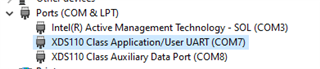
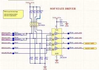
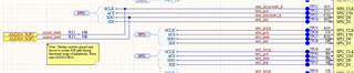
I have the following connections and unable to get the Sitara to communicate over the UART interface when the Sitara is set in UART mode. UART pints are routed to UART0 A7/A6 balls. 


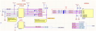
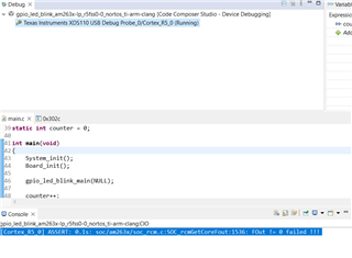
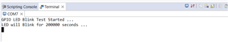
My first thoughts are does the Sitara need to be flashed over JTAG or configured in any way before it will start to talk in UART or should I see the "cccc" being printed out of the box? JTAG seems to be working fine I was able to load code using the Dev Boot Mode. 

  • should I see the "cccc" being printed out of the box?

    After power-up, the AM26x ROM code will print out "cccc" to UART terminal in UART boot mode. 

    does the Sitara need to be flashed over JTAG or configured in any way before it will start to talk in UART

    No, ROM Code will configure any PLLs required during the boot process.

    UART pints are routed to UART0 A7/A6 balls. 

    It is correct. The UART0 (A7, A6) is used for UART boot. ROM Code configures the UART0 to 115200 kbaud, 8-n-1 mode.

    How are the boot mode pins set on your board? For UART boot mode, the pin mapping is [SOP3,SOP2, SOP1, SOP0]=[0, 0, 0, 1]

  • Hi QJ, 

    Yes I have the SOP pins configured to [SOP3,SOP2, SOP1, SOP0]=[0, 0, 0, 1].  Measured voltage is 0, 0, 0 2.995Vdc. 

  • Can you please check if the correct COM port is used in your UART terminal setup?

  • I am connecting to COM7 which is this below in my COM Ports. It disappears when the JTAG is removed. 

  • This is also a new XDS110. Does any configuration need to happen to get the UART bridge active. I see no activity on the RX or TX lines when I probe them. 

  • Can you run an example to see if the debug information can be printed out on UART terminal? 

  • 1. I get the following in the consul when uploading the program to the chip 


    Cortex_R5_0: GEL Output: Loading Gel Files on R5F0
    Cortex_R5_0: GEL Output: Gel files loading on R5F0 Complete
    Cortex_R5_0: GEL Output: ***OnTargetConnect() Launched***

    Cortex_R5_0: GEL Output: AM263x Initialization Scripts Launched.
    Please Wait...


    Cortex_R5_0: GEL Output: AM263x_Cryst_Clock_Loss_Status() Launched
    Cortex_R5_0: GEL Output: Crystal Clock present
    Cortex_R5_0: GEL Output: AM263x_SOP_Mode() Launched
    Cortex_R5_0: GEL Output: SOP MODE = 0x0000000F
    Cortex_R5_0: GEL Output:
    ERR... Reserved boot mode
    Cortex_R5_0: GEL Output: AM263x_Read_Device_Type() Launched
    Cortex_R5_0: GEL Output: EFuse Device Type Value = 0x000000AA
    Cortex_R5_0: GEL Output: AM263x_Check_supported_mode() Launched
    Cortex_R5_0: GEL Output:
    The Device supports both LockStep & Dual Core mode
    Cortex_R5_0: GEL Output:
    mode = 1
    Cortex_R5_0: GEL Output: MSS_CTRL Control Registers Unlocked
    Cortex_R5_0: GEL Output: MSS_TOP_RCM Control Registers Unlocked
    Cortex_R5_0: GEL Output: MSS_RCM Control Registers Unlocked
    Cortex_R5_0: GEL Output: MSS_IOMUX Control Registers Unlocked
    Cortex_R5_0: GEL Output: TOP_CTRL Control Registers Unlocked
    Cortex_R5_0: GEL Output:

    *** R5FSS0 Reset DualCore ***
    Cortex_R5_0: GEL Output:

    ***R5FSS1 Reset DualCore ***
    Cortex_R5_0: GEL Output: R5F ROM Eclipse
    Cortex_R5_0: GEL Output: R5FSS0_0 Released
    Cortex_R5_0: GEL Output: R5FSS0_1 Released
    Cortex_R5_0: GEL Output: R5FSS1_0 Released
    Cortex_R5_0: GEL Output: R5FSS1_1 Released
    Cortex_R5_0: GEL Output:

    All R5F Cores Released for program load
    Cortex_R5_0: GEL Output: L2 Mem Init Complete
    Cortex_R5_0: GEL Output: MailBox Mem Init Complete
    Cortex_R5_0: GEL Output: *********** R5FSS0/1 Dual Core mode Configured********
    Cortex_R5_0: GEL Output: SYS_CLK DIVBY2
    Cortex_R5_0: GEL Output: DPLL_CORE_HSDIV0_CLKOUT0 selected as CLK source for R5FSS & SYS CLKs
    Cortex_R5_0: GEL Output:
    CLK Programmed R5F=400MHz and SYS_CLK=200MHz
    Cortex_R5_0: GEL Output:

    *** Enabling Peripheral Clocks ***
    Cortex_R5_0: GEL Output: Enabling RTI[0:3] Clocks
    Cortex_R5_0: GEL Output: Enabling RTI_WDT[0:3] Clocks
    Cortex_R5_0: GEL Output: Enabling UART[0:5]/LIN[0:5] Clocks
    Cortex_R5_0: GEL Output: Enabling QSPI Clocks
    Cortex_R5_0: GEL Output: Enabling I2C Clocks
    Cortex_R5_0: GEL Output: Enabling TRACE Clocks
    Cortex_R5_0: GEL Output: Enabling MCAN[0:3] Clocks
    Cortex_R5_0: GEL Output: Enabling GPMC Clocks
    Cortex_R5_0: GEL Output: Enabling ELM Clocks
    Cortex_R5_0: GEL Output: Enabling MMCSD Clocks
    Cortex_R5_0: GEL Output: Enabling MCSPI[0:4] Clocks
    Cortex_R5_0: GEL Output: Enabling CONTROLSS Clocks
    Cortex_R5_0: GEL Output: Enabling CPTS Clocks
    Cortex_R5_0: GEL Output: Enabling RGMI[5,50,250] Clocks
    Cortex_R5_0: GEL Output: Enabling XTAL_TEMPSENSE_32K Clocks
    Cortex_R5_0: GEL Output: Enabling XTAL_MMC_32K Clocks
    Cortex_R5_0: GEL Output:

    ***All IP Clocks are Enabled***

    Cortex_R5_0: GEL Output: CPU reset (soft reset) has been issued through GEL.

    2. When trying to run the program I see this message in the Console and the program doesn't run. 


    I have had the program run and got this message in the Serial Terminal. I can't get it to happen again. 

  • I think my problem is related to Boot Mode and SOP 2 and 3 being "Stuck" High. 

    The Console out put shows this Line 
    Cortex_R5_0: GEL Output: SOP MODE = 0x0000000D 

    I have tried messing with the SOP setting and this is the output from 
    SOP       GEL Output
    3 2 1 0    x b b b b
    1 0 0 1    D 1 1 0 1
    0 0 0 1    D 1 1 0 1
    0 0 0 0    C 1 1 0 0
    0 0 1 1    F 1 1 1 1
    1 1 0 0    C 1 1 0 0

    This is how it is wired and is the same as LP dev kit


  • Did you get a faulty switch (SW1)? Did you probe the voltage level of SOP2 and SPO3 pins?

  • I probed the signal and get 0V on the switch input I even shorted the ball directly to ground by connecting the AM263x side of the 10k Ohm resistor directly to ground through a PORz reset and still couldn't change the state.  

  • You connect one pad of R12 and R13 to GND, but you still get wrong SOP GEL output. I checked the ball numbers in your schematics, they are correct (A11, C10). Have you tried another board?

  • Yes R12 and R13 to ground and it doesn't change the GEL output. I tried 2 in the office yesterday. I am working from home today and just have the one with me. 

  • Please try another board next Monday. I'd like to know what causes this issue. Be careful when you connect a pin/ball to GND directly. It may damage your board if the pin or ball is shorted to VCC on your board.

  • Hi QJ,

    I got to the root of the issue. SOP2 and SOP3 lines are repurposed to the SPI lines that I had been externally pulling high one I de-populated those pull ups the chip botted in UART mode. This seems to a hardware issue on my side but thanks for all the help.