This thread has been locked.

If you have a related question, please click the "Ask a related question" button in the top right corner. The newly created question will be automatically linked to this question.

TMS570LC4357: How to configure drivers for RMII using Halcogen?

Part Number: TMS570LC4357
Other Parts Discussed in Thread: HALCOGEN, DP83640, DP83630

Hi,

We have designed a custom board using TI TMS570LC4357 chip. I am using Halcogen to generate the drivers for the peripherals to activate.

I successfully configured drivers for all required peripherals but facing issues in configuring UDP using RMII interface. 

I  am using FreeRTOS, ADC, SPI, UDP and I2C. 

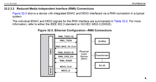
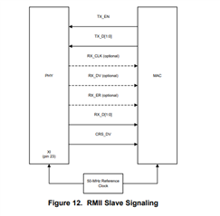
My UDP port using RMII interface is not working. Can you let me know the correct configuration to activate RMII drivers using Halcogen.

Steps I used to activate RMII drivers:

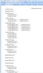
1> Activate drivers as shown below in Halcogen --> Driver Enable Tab:

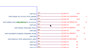
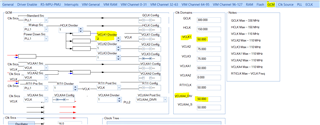
2> Select RMII in PINMUX --> Pin Muxing tab:

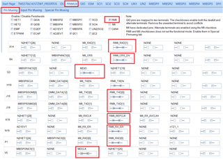
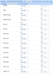
3> PINMUX  --> Input Pin Muxing tab:

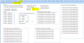
4> Activated RMII in PINMUX --> Special Pin Muxing" Tab:

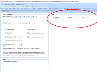
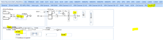
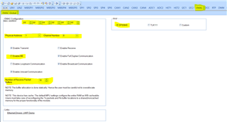
5> In EMAC --> EMAC Global tab:

6> Generate code.

As mentioned and shown above, I performed these configurations in Halcogen followed by generate code, to activate RMII drivers.


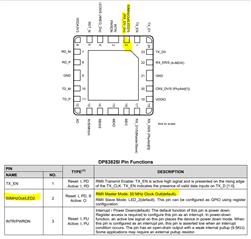
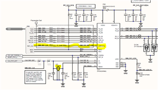
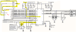
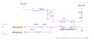
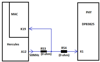
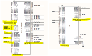
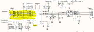
Below is the hardware connections:

Can you please let me know the followings:

Question1 : Are these Halcogen configurations correct or requires more configuration?

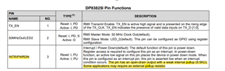
Question 2: Is hardware setup is correct specially MDIO and MDCLK?

Question 3: I am not using Lwip. I am using FreeRTOS functions. Do we have any example how to use Lwip library with  RMII interface, which I can refer ?

Any help will be appreciable. 

Regards

Vivek

  • Hi Jagdish,

    Thanks for your prompt response. 

    I have gone through the links you provided. It make sense.

    But as in my application, PHY (dp83825irmqr ) state that we can use DX_CV as output for 50Mhz clock. Due you think this will be a problem and wont configure for RMII interface? I just want to be double sure before making hardware change to test. Data sheet says  as per below:

    My schematics: 

    Can you verify and guide please. Also is there any demo code which I can refer?

  • Hi Vivek,

    But as in my application, PHY (dp83825irmqr ) state that we can use DX_CV as output for 50Mhz clock. Due you think this will be a problem and wont configure for RMII interface? I just want to be double sure before making hardware change to test. Data sheet says  as per below:

    You can't use DX_CV as output clock to the controller EMAC, because as per PHY datasheet they are saying in RMII master mode only it will generate the 50MHZ clock on the DX_CV right but in our application the RMII master will be the controller and RMII slave will be the PHY.

    So, here my suggestion would be, make the connections as per RMII slave signaling given in Figure-12

    So, use one 50Mhz oscillator and use the clock for both RMII master and slave.

    Can you verify and guide please. Also is there any demo code which I can refer?

    Unfortunately, i don't have any demo code with me, because even HALCoGen doesn't generate the driver for DP83825.

    So, my suggestion would be, select driver for DP83640 and compare the registers and do the necessary modifications required in the driver.

    --

    Thanks & regards,
    Jagadish.

  • So, as per your suggestion, below are my understanding:

    Poin1: Schematics are updated as per below. Is it correct now for RMII interface? Modified sections highlighted. Any feedback on it?

    Point 2: I still have a one more doubt regarding clock. You specified in your last suggestion to keep 50Mhz for PHY and for MAC. I changed the crystal of PHY from 25MHz to 50MHz. But MAC is with TMS570LC4357 chip. So, do to mean to say that I need to change the crystal of my tms570 as well with 50MHz.  As per TMS570 datasheet, 50MHz is beyond its recommended rating. 

    I believe, I misunderstood that point of yours. Can you please elaborate so that I understand that point effectively. Currently my TMS570 is connected with 16MHz. 

    Point 3: Other thn DX_CV pulled high. I also have pullup on MDIO. Any other pin require pullup?

    Point 4: PHY

                 4.1: In which file halcogen generate drivers for DP83630. 

                 4.2: I thought drivers for DP83630 and DP83825 will be same as they are same family with minor changes. 

                 4.3:  Do TI provide drivers for  DP83825 ?

  • Hi @jagadish gundavarapu ,

    To get the 50MHz from MAC to the PHY, we can configure TMS570LC4357 chip  EMAC --> ECLK1 (ball A12).

    I configured it using Halcogen. Can you confirm the below halcogen configuration to get 50MHz output at A12?:

    Step 1: 

    Step 2: 

    Are these two steps enough to generate 50MHz output at A12?


  • Hi Vivek,

    Apologies for the delay in the response.

    Point 2: I still have a one more doubt regarding clock. You specified in your last suggestion to keep 50Mhz for PHY and for MAC. I changed the crystal of PHY from 25MHz to 50MHz. But MAC is with TMS570LC4357 chip. So, do to mean to say that I need to change the crystal of my tms570 as well with 50MHz.  As per TMS570 datasheet, 50MHz is beyond its recommended rating. 

    Please don't change the controller crystal. What i am saying is we should also need to provide the 50MHz clock to the RMII_REFCLK pin of the controller.

    The highlighted pin also requires the 50Mhz clock in in RMII mode. 

    Poin1: Schematics are updated as per below. Is it correct now for RMII interface? Modified sections highlighted. Any feedback on it?

    Please route the 50Mhz clock of the crystal to the RMII_REFCLK pin of the controller also.

    Something like below:

    As you can see in above pic, here they are routing crystal 50Mhz clock output to the both PHY and RMII_REFCLK of the controller pin also right.

    You can find above schematic in below link:

    TMDX570LC43HDK Development kit | TI.com

    Point 3: Other thn DX_CV pulled high. I also have pullup on MDIO. Any other pin require pullup?

    I don't think even RX_DV pin also requires a pullup. I found in datasheet only about MDIO pin requires pullup.

    And maybe you can use pullup for INTR/PWRDN as per datasheet suggestion.

    Point 4: PHY

                 4.1: In which file halcogen generate drivers for DP83630. 

                 4.2: I thought drivers for DP83630 and DP83825 will be same as they are same family with minor changes. 

                 4.3:  Do TI provide drivers for  DP83825 ?

    The driver will be present in the HL_phy_dp83640

    TI will not provide DP83825 drivers. Please verify the drivers generated for DP83640.

    --
    Thanks & regards,
    Jagadish.

  • Hi Jagidsh,

    Thanks alot for your response. I understood your approach now.

    My hardware (PCB) have a provision to configure pin/ball A12.

    TMS570LC4357 chip EMAC --> ECLK1 (ball A12).

    Do you think that will work? If yes, can you confirm the steps I followed in Halcogen to configure A12 for 50MHz output for PHY, is correct?

    Screenshots attached in my previous response for A12.

  • Hi Vivek,

    TMS570LC4357 chip EMAC --> ECLK1 (ball A12).

    Do you think that will work?

    ECLK(External clock) pins are different, they are not related to the EMAC of the controller. They are the pins used to output the clock.

    You should use only RMII_REFCLK that is K19.

    --
    Thanks & regards,
    Jagadish.

  • Hi Jagadish,

    Are you sure we can use K19 as 50MHz clock output from MAC? 

    Technical reference manual of TMS570LC4357 only specify it as input pin (when PHY is master). There is no info about PHY in slave and K19 output 50MHz from EMAC.  


    Also, if its true that we can use it to output 50MHZ from EMAC, can you guide how to configure it in halcogen. (if possible, with some screenshots).

  • Hi Vivek,

    Are you sure we can use K19 as 50MHz clock output from MAC? 

    I am not saying we will get 50Mhz output from K19 pin. I am saying, we have to connect the 50Mhz oscillator clock as reference to the K19 pin. I mean just route the 50Mhz output from crystal to both controller K19 and PHY like as shown below:

    --
    Thanks & regards,
    Jagadish.

  • Thanks for this clarification. 

    Is it possible not to use a 50MHz of crystal for PHY?

    Rather than connecting 50MHz crystal with PHY, how about if we generate 50MHz from ball/pin A12 and route this 50MHz reference clock to K19 and PHY X1 (image shown below). Will that work?


  • Hi Vivek,

    Is it possible not to use a 50MHz of crystal for PHY?

    Rather than connecting 50MHz crystal with PHY, how about if we generate 50MHz from ball/pin A12 and route this 50MHz reference clock to K19 and PHY X1 (image shown below). Will that work?

    There is no clear document to conclude this but i found couple of threads and there they are saying we can avoid external crystal.

    (13) TMS570 VCLKA4 requirements for EMAC (TMS570LS1227 & TMS570LS3137) - Arm-based microcontrollers forum - Arm-based microcontrollers - TI E2E support forums

    (13) CCS/RM48L952: RM48L952-LWIP Design for DP83848 - Arm-based microcontrollers forum - Arm-based microcontrollers - TI E2E support forums

    So, my suggestion here would be, if you have a prototype board then just give a try and test it.

    --
    Thanks & regards,
    Jagadish.