I am experiencing a very strange high-temperature failure in the TM4C1233H6PMI that is somehow related to its U5 UART receiver. Summary: The U5Rx pin (pin PE4) goes from high impedance to low impedance starting at the fifth incoming UART data bit. Here is the relevent circuit diagram.
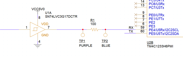
The buffer drives PE4 using 5V logic, which is acceptable according to the TM4C1233H6PMI datasheet. Everything works properly at temperatures below roughly 70 C. Once the temperature exceeds 70 C, PE4 seems to transition from high impedance to low impedance before it receives UART data bit #5 when I send it 0x53 (recall that UARTs send LSB first). It stays at low impedance until the temperature decreases, at which time everything returns to normal operation. The purple and blue oscilloscope traces below correspond with the test points in the circuit diagram above.
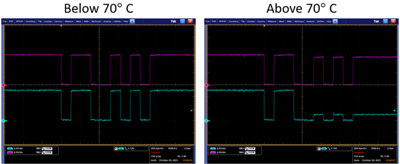
This failure is completely repeatable. The change to low impedance always happens at the same UART bit. The relationship between UART receive, pin impedance, and temperature has me baffled. Here are a few other notes I've made.
1. If I send 0xFF to the UART it never fails
2. If I use a 1k ohm series resistor instead of the 100 ohm resistor it never fails
3. If I drive PE4 with 3.3V logic instead of 5V logic it never fails
Items 2 and 3 decrease the additional heat generated in the TM4C1233, so I'm not completely surprised that they help.
I would appreciate any insights into what may be going on, or suggestions for additional tests I could run.
Thanks,
Mike