Other Parts Discussed in Thread: TIDA-020047, SYSCONFIG, TMP112, MSP430F5529
Hi team
A new thread is posted as below thread is closed.
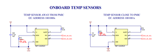
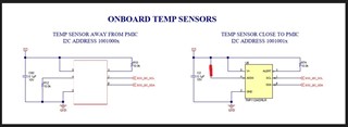
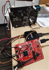
It seems TIDA-020047 also has R78 and R81 as pull-up resistors,
Customer try to call I2C_transfer directly (bypass I2C_probe). The waveform in TIDA_020047 and AM2732EVM shows very different results.
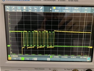
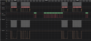
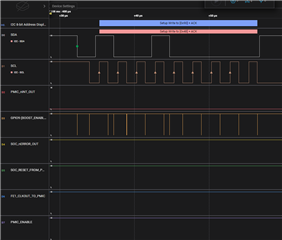
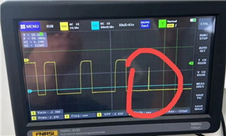
on TIDA020047, code return NACK error. Waveform is as below:
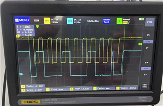
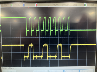
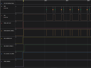
on AM2732EVM, code did not show any NACK error. Waveform is as below:
Could you pls help comment on the reason why the wave form looks so different?
Thanks
Ken