This thread has been locked.

If you have a related question, please click the "Ask a related question" button in the top right corner. The newly created question will be automatically linked to this question.

TMS570LS3137: PWM Capturing Code is working incorrectly

Part Number: TMS570LS3137
Other Parts Discussed in Thread: HALCOGEN

Hello Everyone,

I'm using TMS570LS3137 microprocessor for our project.

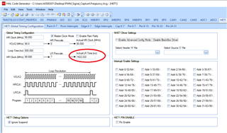
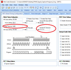
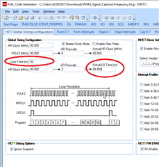
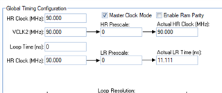
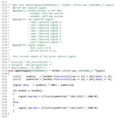
We have to capture a PWM frequency with TMS570 HET port. We used the Halcogen generated HET library for this. But capGetSignal working incorrectly. We realised it works like this:

Constantly measures values up to certain frequencies like this:

Applied PWM Freq            Captured PWM Freq

90kHz                                100.4kHz

92kHz                                100.4kHz

96kHz                                100.4kHz

98kHz                                100.4kHz

99kHz                                100.4kHz

100kHz                              100.4kHz

102kHz                              117.187kHz

104kHz                              117.187kHz

106kHz                              117.187kHz

108kHz                              117.187kHz

110kHz                              117.187kHz

120kHz                              140.652kHz

It seems to output only one frequency over a certain range.

We don't understand why sihft right this period?

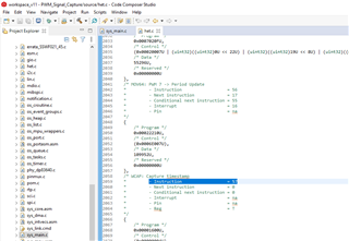
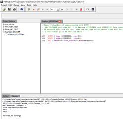
We test codes is this:
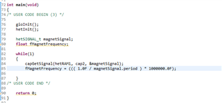
Thanks.

  • Hi Ali,

    We started working on your issue and will provide an update ASAP.

    --

    Thanks & regards,
    Jagadish.

  • Hi Jagadish,

    Good to see u.

    Thank you,

    Best Regards,

    Ali.

  • Hi Ali,

    Is it possible to share the project, may not be original at least a sample project with the issue?

    Because this will helpful to test it and debug it.

    --
    Thanks & regards,
    Jagadish.

  • Hi Jagadish,

    Yes it is possible. Here is a project for PWM Capture. We used this sample project.

    On the other hand we measured and approved the generated PWM signals with an oscilloscope. But generated and captured signals do not match.

    Thank you

    Best regards.

    Ali.

    PWM_Signal_Capture.zip

  • Hi Ali,

    Apologies for the delay in my response.

    I was stuck with other issues, didn't get enough time to spend on this issue. 

    Are you still stuck with this issue?

    --

    Thanks & regards,
    Jagadish.

  • Hi Jagadish,

    No problem. I know how busy you've been.

    Yes I still stuck with this issue.

    Thank you

    Best regards.

  • Hi Ali,

    I just tested the condition 120Khz and i got the same value as yours 140.6Khz. I am just analyzing the code now and i will provide you an update ASAP.

    --
    Thanks & regards,
    Jagadish.

  • Hi Jagadish,

    We founded a temporary solution for this but We are not sure that it will work reliable.

    Can you control this code. We revised capGetSignal function with this (shift right 7 changed to 0)

    void capGetSignal(hetRAMBASE_t * hetRAM, uint32 cap, hetSIGNAL_t *signal)
    {
        uint32    pwmDuty   = (hetRAM->Instruction[(cap << 1U) + 25U].Data) >> 7U;
        uint32    pwmPeriod = (hetRAM->Instruction[(cap << 1U) + 26U].Data) >> 0U;
    
        signal->duty   = (pwmDuty * 100U) / pwmPeriod;
        signal->period = pwmPeriod;
    }

    By followed, we got received frequency with this calculation :
    fFrequency = ( ( ( 1.0F / pwmperiod ) * 1000000.0F ) / 11.10F ) * 1000;

    I hope it helps you

    Thanks.

    Regards

    Ali.

  • Hi Ali,

    Is your temporary workaround is working for entire frequency range?

    Actually, i understood the real route cause for the problem. The problem is due to the large amount of LR (Loop Resolution) time.

    LR time in our case is equal to the 1.422uS. Actually, the values we are seeing are not wrong values, they are just expected values only.

    Here the period is measured by using loop resolutions, i mean for example if we need to measure a period between two raising edges then we will start increment a register value after first raising edge and we continue to increment the register value after each loop and this process will continue till other raising edge has been reached.

    Now the period = register_count (Number of loop resolutions) * One loop resolution Period.

    If you analyze above formula, there should be max of one loop resolution period error would be possible, I mean

    Measured_Period = (Actual_Period) to (Actual_Period + One_Loop_Resolution_period).

    For example, if you are trying to measure 120Khz frequency (8.33uS period) then imagine if your loop resolution is sampled at 8.29uS then it will again do the next sample at 8.29 + 1.422 to calculate the period.

    So, Measured_Period = 8.33 to (8.33 + 1.422)

    So, the measured value can be anywhere in between 8.33uS to 9.752uS

    If you, covert this into frequency it can be in between 120Khz to 144.759Khz. That is the reason why we got 140Khz while measuring 120Khz.

    So, the only way to measure accurate frequency would be by reducing the loop resolution period. But again, we can't reduce it as much as we want because the loop should have enough time to execute the largest path in the program. 

    In HALCoGen generated code, we have 58 instructions

    And the execution frequency for each instruction is 90Mhz, so the least LRP possible would be 58*(1/90Mhz) = 644nS. 

    You can just try below configuration:

    It will reduce the error at some extension.

    But if you want to further reduce it, then you should go for HET IDE, here you can generate a minimal code something like below:

    See here i just used 3 instructions, to measure duty cycle and period and duty cycle of waveform on pin30. As we have only 3 instructions, this would just require 33nS to execute. So in this case i just configured 88nS and executed and i got very accurate results.

    I am attaching my code for your reference.

    PWM_Signal_Capture (2).zip

    --
    Thanks & regards,
    Jagadish.

  • Hi Jagadish,

    Thank you for all.

    Is your temporary workaround is working for entire frequency range?

    It is the LR pre-scale parameter that you are changing. This makes the same change as the workaround we found. We found the solution without realising it :)

    Can you control this code. We revised capGetSignal function with this (shift right 7 changed to 0)

    Look this, we removed 7 bit shift right operation and we changed multiplication with 1422 to 11.1. This revision the same result as making the loop time 0. Look like:

    I totally get it. Thank you very much.

    Brilliant

    Best regards & Thanks.

    Ali