Hi TI team!
I found interesting behavior, but I can not explain that. Please help.
I measure ADC input in two ways:
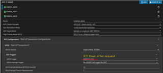
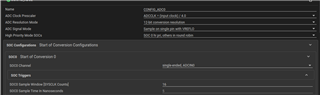
- Periodically (every 10 ms for example). SOC trigger is the ePWM
- By request, with a different frequency, at a short period. SOC trigger is the RTI timer.
The lines where I measure current, I observe the next situation:
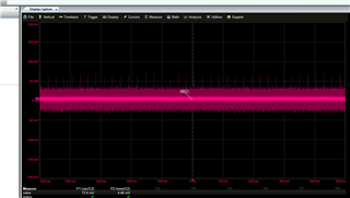
- Periodical report stable in raw values: for example I get 100 counts +- 2% every 10 ms.
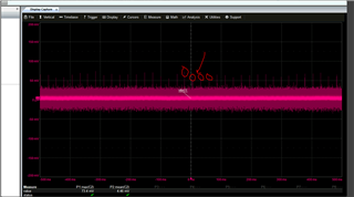
- When I request measurements on the high frequency with 1 uS, I observe the next behavior: each next measurement gives me higher values than previous, for example, 100, 120, 140,160...300 I have 32 measurements, and the last one gives me three times larger than the first.
All other lines where I do voltage measurement do not increase values.