Part Number: MSP432E401Y
Hi team,
I have a customer who has given the below requirements/specs for an MCU they're trying to design in for a rebuild of a license plate reader system. They've given a couple ideas on MCUs they're currently looking into and system-level concerns they'd need appeased. I did look into your MSP Excel cross tool for the PIC32MZ0512 and the MSP432 did come up, so that's why I've put that down as the PN for this thread (could be totally incorrect, though). Let me know your thoughts on the below details
"Microcontroller for high temperature camera.
This project is in early states of R&D.
These are the 2 microcontrollers that I found that look promising:
Renesas R9A07G074M04GBG
Microchip PIC32MZ0512EFE064-I/PT
Here are some of the parameters we identified
- We need a microcontroller that will interface with an image sensor IC, receive that sensor’s image data, and transmit that data to a windows PC via USB 2.0.
- We will probably use one of the OnSemi image sensors that has a parallel data interface such as AR0237AT.
- Most of these image sensors have a parallel data interface that should be compatible with a general-purpose IO interface that is found on most microcontrollers.
- Microcontroller should be in a small package.
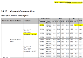
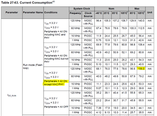
- It’s not sufficient just to know that the microcontroller is rated for 100C ambient temperature. To estimate whether the processor will operate at 100C ambient, we need to make some calculations. This is how I have been evaluating:
- Calculate the power that can be dissipated by the specific IC package. Take for example this processor: PIC32MZ0512EFE064-I/PT. From the datasheet, the thermal impedance qJA of the 64-pin TQFP package is 49 °C/W. This part is rated for max Tj of 140C. The maximum dissipation would be (140 – 100) / 49 W = 816mW.
- Estimate how much power must be dissipated by the processor for this application. In this example, we could assume the Idd for core and IO voltage is about 100mA. Minimum operating voltage of 2.1V would mean 210mW dissipation. But that doesn’t include the dissipation of the USB & the USB PLL. I didn’t find that data in the datasheet but I’m guessing from other experience that this would be about 60mA at 3.3V = 198mW. If there are no other significant loads then this may be a good candidate. I estimated a total of 408mW, well under the 816mW maximum.
- But also, we need for the IO voltage to be in a range that is compatible with the IOs of the image sensor IC. If we have to raise the processor’s Vdd then that increases dissipation."
Thanks in advance!
Marco