This thread has been locked.

If you have a related question, please click the "Ask a related question" button in the top right corner. The newly created question will be automatically linked to this question.

MSP432E401Y: LAN problem

Part Number: MSP432E401Y

Hi TI!!!

I have designed a board that does not have a working LAN. The power supply is OK and the MCU works, but the LAN does not work. Attached is the schematic of the MCU and the LAN.

Do you see any reason why the LAN is not working?

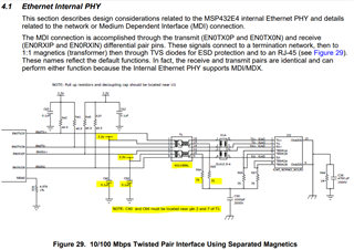
Framed in red box I show some stubs that I have in the pcb. The stubs are different (they are not symmetrical) with a maximum length of 16mm and width 1.524mm.

Framed in red box I show the passive components of the LAN connector. I have used this same schematic in another project (not with MSP432) and it works perfectly.

Please, check the MSP432.pdf file with the shematic

MSP342.pdf

  • Hi,

      Can you take a look at the schematic and compare with the TI Reference Design that implements POE? TM4C129 is the same silicon as MSP432E. 

    https://www.ti.com/tool/TIDM-TM4C129POE

    https://www.ti.com/tool/TIDM-TM4C129POEAUDIO

  • Hi Charles, thank you very much!

    I have reviewed the designs you share with me, I don't see anything significant with respect to my design. The RJ45 is with integrated POE and in my case it is with external components but basically it is the same.

    Please could you take a look at the shared design to see if anything is wrong.

    Thanks very much.

    Best regards.

  • Hi,

       Where do the stubs go? Are they just open? Reading the RJ45 POE pinout, pin4,5 are for DC+ but yours seems to connect to POE_B- rather than POE_B+. I must say I'm not an expert in POE. I don't know if that is worth looking into. 

  • Hi Charles,

    Thanks very much,

    The stubs are just open.

    In the scheme PoE_B+ and PoE_B- they go to a rectifier diode bridge before powering the circuit, so polarity should not be a problem.

    Note this difference in my design compared to the MSP432E401Y LaunchPad:

    The MSP432E401Y LaunchPad uses a transformer (HX1198FNL T) with the filter on the side of the chip, in my case I used a transformer (HR641680E) with the filter on the side of the RJ45 connector. But this shouldn't be a problem, or am I wrong?

    MSP432E401Y LaunchPad

    My board:

  • Hi,

      Please refer to section 4.1 MSP432E System Design Guideline for best practices. The transformer in the design guideline has the same orientation as yours so I think it should be fine from that perspective. As you are already aware the recommended transformer is HX1188FNL showed in the TRM and HX1198FNLT implemented on the LP. This is not to say you cannot use HR641680E by similarity. It will be good to check with the manufacturer for their assessment of suitability. One thing I notice on your schematic is that the center tap is not filtered but rather connected to 3.3V only. However, I don't know if this is what caused the Ethernet to not work. Please refer to the design guideline on the center tap connection. I will suggest you probe the differential pairs and compare between LP and your board to see if it will reveal any hints. 

    The center tap of the transformer (microcontroller side of the transformer) should be connected to 3.3 V. Each connection point to the 3.3-V rail must be adequately filtered with a capacitor (0.1 µF or greater) if a solid power-plane is present (C40, C60 in Figure 29). If the center tap connects to a PCB trace instead of a plane, the capacitor value should be 1 µF or greater.

  • Hello Charles

    We finally found the problem, we had not assigned MAC address.

    Thanks very much.