This thread has been locked.

If you have a related question, please click the "Ask a related question" button in the top right corner. The newly created question will be automatically linked to this question.

TMS570LC4357: SIMO[3:0] output bits issue

Part Number: TMS570LC4357

Hi Team,

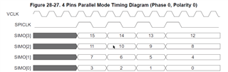
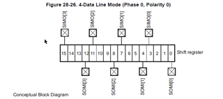
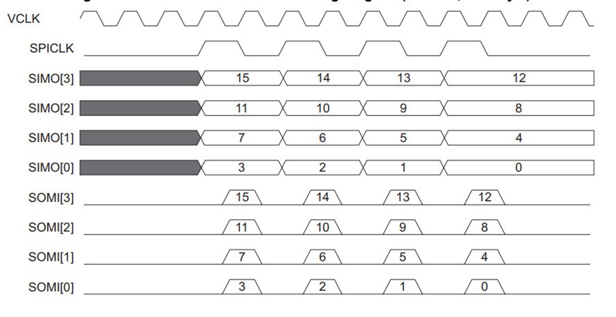
The MibSPI module outputs 15,14,13,12 for 4-wire 16-bit data instead of 15,11,7,3bits.

The customer would like to know why this model is only supported? Is there a way making it possible to switch to SIMO[3:0] to output 15, 11, 7, 3 bits, respectively?

Could you help check this case? Thanks.

Best Regards,

Cherry

  • Hi Cherry,

    Is customer saying, he is not getting output as per the TRM waveforms in parallel mode?

    If that is the case, then i got waveforms as per the TRM only.

    As you can see i am sending the data 0xC3A5, in 4 line parallel mode and here is the output waveforms i got:

    As you can see

    MO3 - bit-15, bit-14, bit-13, bit-12  = (1, 1, 0, 0)

    MO2 - bit-11, bit-10, bit-09, bit-08  = (0, 0, 1, 1)

    MO1 - bit-07, bit-06, bit-05, bit-04  = (1, 0, 1, 0)

    MO0 - bit-03, bit-02, bit-01, bit-00  = (0, 1, 0, 1)

    The output is exactly as per TRM only:

    I am attaching my code for your reference:
    MibSPI_Parallel_Mode_TEST_LC4357.zip

    --
    Thanks & regards,
    Jagadish.

  • Hello Jagadish,

    Thank you for the support.

    The customer case here is if it's proper to output in the following format since some of their devices output like this:

    MO3 - bit-15, bit-11, bit-07, bit-03 

    MO2 - bit-14, bit-10, bit-06, bit-02 

    MO1 - bit-13, bit-09, bit-05, bit-01 

    MO0 - bit-12, bit-08, bit-04, bit-00

    Also, 

    The customer would like to know why this model is only supported?

    The customer is wondering why TMS570LC4357 only support the model as posted in the original thread. And what are the main applications for this output?

    Thanks and regards,

    Cherry

  • Hi Cherry,

    The customer is wondering why TMS570LC4357 only support the model as posted in the original thread. And what are the main applications for this output?

    I don't know exact reason why they implemented in this way. My understanding is that it is an easy way and can improve the throughput. Because,

    Just consider MO3 is hardwired at bit-15, MO2 is hardwired at bit-11, MO1 is hardwired at bit-7 and MO0 is hardwired at bit-0. On first clock pulse the bit-15 will be moved out on MO3, bit-11 will be moved out on MO2, bit-7 will be moved out on MO1 and bit-3 will be moved out on MO0 right, so for next clock pulse the data in the shift register can be shifted by one bit left, that's it nothing else to do. Now bit-14 will be on MO3, bit-10 on MO2, bit-6 on MO1 and bit-2 on MO0. And for next clock pulse the data will be left shift by 1 again and this continuous. See this is an easy way and it is a high throughput way right? May be this is the reason they implemented like this.

    Unfortunateley there is no hardware mechanism to get data as customer requested but we can do that in software.

    I mean what if we change the bit positions before we are sending out the data to the slave and what if we change the bit positions after we are receiving the data from the slave. This will rectify the issue, right?

    To test this software workaround, i did the following steps:

    1. I just created two-bit field structures based on the order for Master and slave.

    2. I also created one "Converting_Master_to_Slave_Format" API, this API will be helpful while sending data to the slave and this API will convert the Master bit order in according to the slave bit order before we are sending the data.

    3. Similarly, i created another API called "Converting_Slave_to_Master_Format", this API will be helpful to convert the received data from slave into the master order.

    Yes, obviously this method will reduce the throughput at some extent as we need to convert every frame of received or transmitted data. But unfortunately, there is no other way to interface with slave device as there is a protocol mismatch.

    I am attaching my complete project for your reference:

    3487.MibSPI_Parallel_Mode_TEST_LC4357.zip

    --
    Thanks & regards,
    Jagadish.