Part Number: MSPM0L1306
Other Parts Discussed in Thread: SYSCONFIG
Hi Champs!
Customer is finalizing his 1st MSPM0L PCB and raised some BSL/pin related questions:
1.
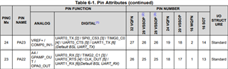
For the ADC we will use an external reference voltage source (REF3025). We will feed VREF+ via PA23 to pin 27 and VREF- is identical to GND.
Do we need to connect PA21 to GND at pin 25 or can we use this pin for other purposes?
Several points in the documentation suggest that a different use of PA21 on pin 25 could be possible.
But in the TRM, chapter 9.2.2 says "When supplying an external reference to the ADC, Connect the VREF+ PIN to the reference source with the appropriate decoupling circuit, and Connect the VREF- PIN to ground."
2.
We would like to provide a way to update the firmware.
It should not be available to our customers, but our application engineers should be able to use it easily.
The bootstrap loader (BSL) should communicate via UART0, but use different pins than the same UART used for the internal diagnostic interface for firmware development.
As on the Launchpad, we have provided PA8 and PA9 for the diagnostic interface, and we would like to use pre-configured pins for the BSL as much as possible by TI.
Unfortunately, I am not sure about the pins preconfigured by TI.
Which pins does TI pre-configure for the BSL?
If we cannot use the preconfigured pins, we could initially configure the alternative pins in the configuration memory (NONMAIN) ourselves.
We would like to avoid that.
3.
The Users Guide for the MSPM0 bootloader (SLAU887) describes an "Interface Autodetection" phase.
Does this phase take into account the pin configuration for the UART0 configured by TI or by us?
Thanks in advance!