Part Number: MSPM0L1306-Q1
Other Parts Discussed in Thread: SYSCONFIG
Hello
I'm trying to create a simple program to configure GPIO on our board. I'm planning on creating a bare bones program without using Driver Lib (using it as a sort of a reference though). Looking at the overview for the GPIO module it looks like the starting point is the creation of the GPIO_PinConfig array, with each element corresponding to a pin on the MCU.
I have some questions on this listed below:
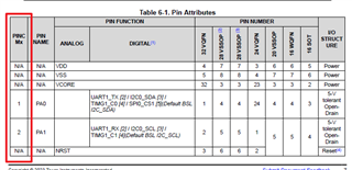
- What happens to pins that are multiplexed?
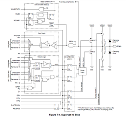
- The documentation has no description of IOMUX module and how it interplays with this one. Can you help me with it?
- Example GPIO projects in Code composer studio (CCS) always start with configuring the IOMUX module before it actual starts working with GPIO registers. This isn't reflected in driverlib documentation. Am I missing something here?
- What happens in case of different pin configurations? Each of them have a different GPIO count now isn't it? Shouldn't this be reflected in the code as well?
Here is a piece of code in one (of many) example projects provided as part of CCS that initializes the GPIO module:
SYSCONFIG_WEAK void SYSCFG_DL_GPIO_init(void)
{

    DL_GPIO_initDigitalOutput(GPIO_LEDS_USER_LED_1_IOMUX);

    DL_GPIO_initDigitalInputFeatures(GPIO_SWITCHES_USER_SWITCH_1_IOMUX,
        DL_GPIO_INVERSION_DISABLE, DL_GPIO_RESISTOR_PULL_UP,
        DL_GPIO_HYSTERESIS_DISABLE, DL_GPIO_WAKEUP_DISABLE);

    DL_GPIO_setPins(GPIOA, GPIO_LEDS_USER_LED_1_PIN);
    DL_GPIO_enableOutput(GPIOA, GPIO_LEDS_USER_LED_1_PIN);
    DL_GPIO_setLowerPinsPolarity(GPIOA, DL_GPIO_PIN_14_EDGE_RISE_FALL);
    DL_GPIO_clearInterruptStatus(GPIOA, GPIO_SWITCHES_USER_SWITCH_1_PIN);
    DL_GPIO_enableInterrupt(GPIOA, GPIO_SWITCHES_USER_SWITCH_1_PIN);

}
Wading into `DL_GPIO_initDigitalOutput`, I see it looks like this:
__STATIC_INLINE void DL_GPIO_initDigitalOutput(uint32_t pincmIndex)
{
    /* GPIO functionality is always a pin function of 0x00000001 */
    IOMUX->SECCFG.PINCM[pincmIndex] =
        (IOMUX_PINCM_PC_CONNECTED | ((uint32_t) 0x00000001));
}
Could you expand on this a bit?