This thread has been locked.

If you have a related question, please click the "Ask a related question" button in the top right corner. The newly created question will be automatically linked to this question.

AM2634-Q1: manual setting of pinmux

Part Number: AM2634-Q1
Other Parts Discussed in Thread: AM2634, SYSCONFIG

Dear Champs,

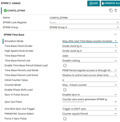
Could you please check if it is possible to set pinmux manually to PWM after setting PWM register in AM2634?

e.g.

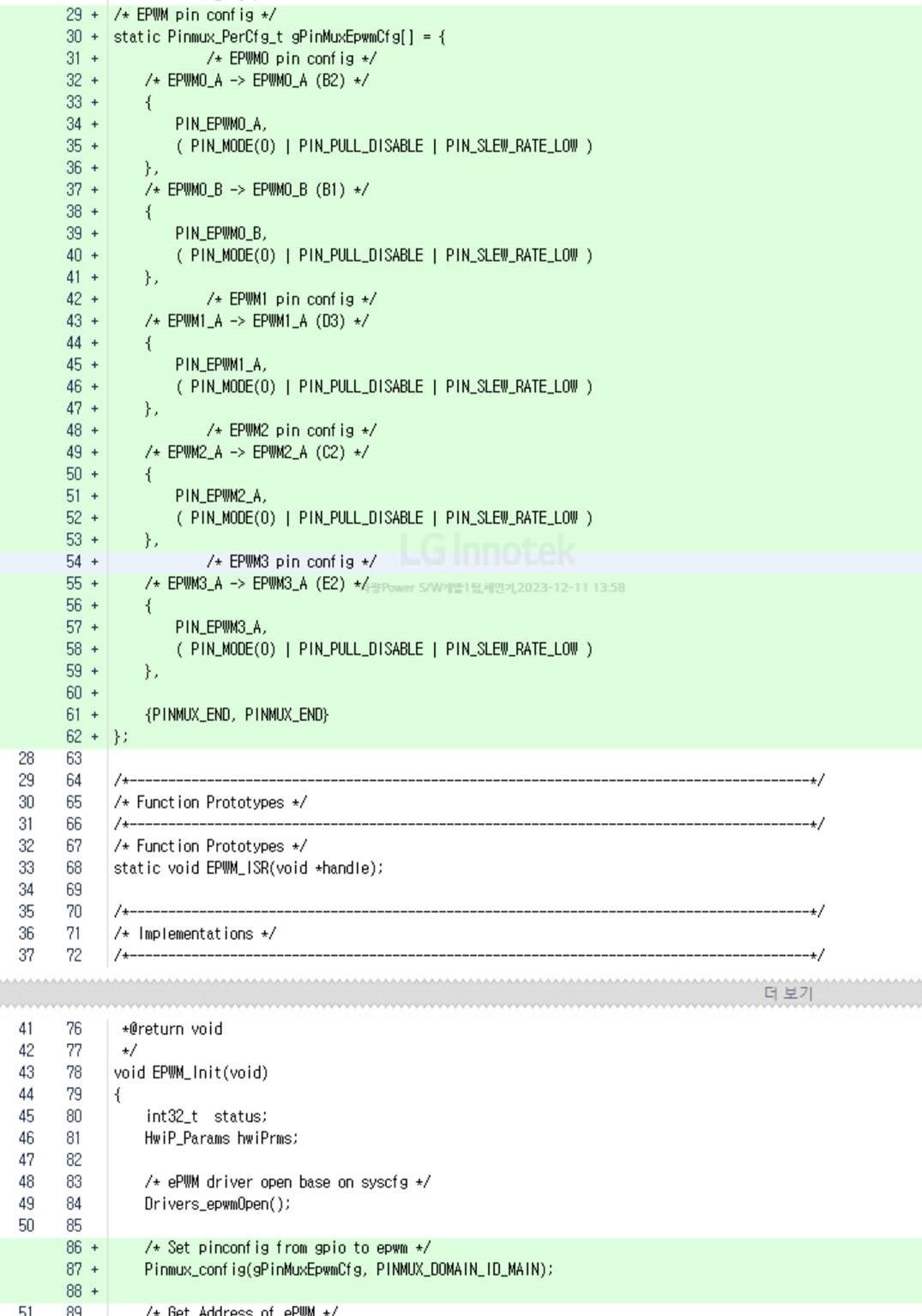
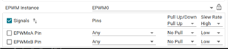
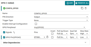
1) to generate PWM signal after setting PWM register configuration, my customer set PWM pins to GPIO at initial time.

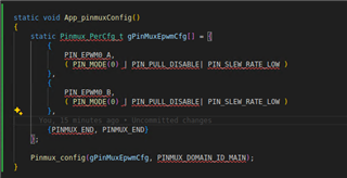
2) After booting, customer set PWM register and modify pinmux to set these pins to PWM.

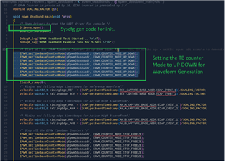
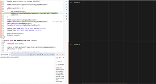
Is this possible? When customer tried it using sysconfig generated code, they found it would be go to exception when pinmux changing after PWM register setting.

Thanks and Best Regards,

SI.

  • Hi SI,

    This should be possible.

    This should not get to any exception so long as IOMUX registers are configured properly, with IOMUX unlocking and locking. Could you please let me know which PWM pin are they trying to configure, so I can check and update here? Also if possible the snippet of code they are using to configure too.

    Thanks and regards

    Madhava

  • Hi Madhava,

    Thanks for your response.

    The below is sysconfig snapshot and they configured it as GPIO as below.

    When they set it as pwm as below, they faced exception. Should they configured it as PWM before PWM setting in Drivers_epwmOpen()?

    But, their target is to remove unexpected signal before PWM setting and they should set PWM configuration before pin configuration changed.

    Thanks and Best Regards,

    SI.

  • Hi SI,

    Could you please share the exception the code is throwing?

    Usually Pinmux is tackled way earlier in the application, and not changed while execution. I have tried to replicate what you have shared, no exception observed.

    Anyways, if the required result is to attain PWM waveform only after configuring all, then there are 2 ways.

    1. From within the IP: 
      1. Keep the timebase counter in freeze mode, while configuring the rest of the sub-modules.
      2. then configure it to a required mode like up-count/ down-count/ up-down-count.
      3. this will enable the TBCounter to run only after all the configurations that are needed are done.
    2. From  Global Control:
      1. we can identify "SOC_setEpwmTbClk" being called for the epwm configurations in the syscfg generated code.
      2. This API configures the enable/disable of the EPWM Time base Clock. 
      3. with this, disabled, even if the Timebase counter mode is not "stop and freeze", the counter wouldn't run and we can configure the epwm configurations and then once done, we can enable this global control and get the timebase counter running and resulting in the output.
  • Hi Madhava,

    The exception was not observed anymore in customer side also when pinmux was changed, but it seems pin mode was not changed properly at this time. In your test, have you successfully changed it using modifying pinmux register?

    For your suggestions, could you please provide more details and examples?

    For Global Control, I found the 'SOC_setEpwmTbClk' API were set to 'True' in system_init() function generated by sysconfig, but I'm curious how this can be changed to 'False' because this file & function were generated at every build time.

    My customer found below high pulse while setting epwm A/B.

    Thanks and Best Regards,

    SI.

  • HI SI,

    In your test, have you successfully changed it using modifying pinmux register?

    Yes, I was able to set the pinmux successfully using the above suggested method. 

    For your suggestions, could you please provide more details and examples?

    Sure.

    For (1) please refer the AM263x MCU+ SDK: EPWM Deadband (ti.com) example. Please note how the timebase counter is set to 0, the epwm outputs are not setting high on counter=0 event (where the counter is currently at 0) and the counter mode is set to "stop and freeze", then the configurations are done, then within the application the example sets the timebase counter modes to up_down mode.

    For (2), we do not have a direct method as such. you can choose to not generate the ti_drivers_config.c file and link it as a separate file in the project. Anyways, Let me check with the team on the adding the support from the syscfg, if we can choose not to set to "true" for this API MCUSDK-12608

    My customer found below high pulse while setting epwm A/B.

    Could you please help me which waveforms correspond to which PWM instance/ outputs? 

    thanks and regards,

    Madhava

  • Hi Madhava,

    My customer found below high pulse while setting epwm A/B.

    Could you please help me which waveforms correspond to which PWM instance/ outputs? 

    They tried to set as below.

    1. EPWM pinmux setting

    2. EPWM A/B complementary operation setting(EPWMB channel inverting mode set through Dead band)

    3. For low output of EPWM A/B in Action Qualifier,  EPWM A set to low and B set to high in Continuous SW Force Action.

    After above 2, there was high output in EPWM B pin as above.

    Thanks and Best Regards,

    SI.

  • Hi SI,

    Apologies, I see there are three waveforms in the image you have shared. I am hoping them to be (1) EPWM A [low input], (2) EPWM B [high input], (3) signal [pulse]. could you please label them and help me understand on which the pulse is observed. Also, which EPWM instances are showing unexpected behavior?

    thanks and regards,

    Madhava

  • Hi Madhava,

    Apologies, I see there are three waveforms in the image you have shared. I am hoping them to be (1) EPWM A [low input], (2) EPWM B [high input], (3) signal [pulse]. could you please label them and help me understand on which the pulse is observed. Also, which EPWM instances are showing unexpected behavior?

    Brown line - EPWM A output, Red line - EPWM B output(pulse observed at around +0.5ms)

    For (1) please refer the AM263x MCU+ SDK: EPWM Deadband (ti.com) example. Please note how the timebase counter is set to 0, the epwm outputs are not setting high on counter=0 event (where the counter is currently at 0) and the counter mode is set to "stop and freeze", then the configurations are done, then within the application the example sets the timebase counter modes to up_down mode.

    When I checked Deadband example in the MCU+SDKv9.1, I found below settings in sysconfig, and want to check what you explained are red circles in below.

    Could you please let me know what you explained are the below settings(red circle) in sysconfig?

    I found below codes were generated in system_init() of ti_drivers_config.c. The settings in sysconfig what you explained generated below codes(blue circle)?

    And, I found customer is using MCU+SDK v8.5.0. Does this also supported on MCU+SDK v8.5.0?

    Thanks and Best Regards,

    SI.

  • HI SI,

    I am still confused about the waveforms, as you have mentioned that A is sw-forced to low, B is sw-forced to high, but from the waveforms, it looks opposite. could you please confirm with the customer whether, white is A, brown is B, or as you've mentioned? 

    3. For low output of EPWM A/B in Action Qualifier,  EPWM A set to low and B set to high in Continuous SW Force Action.

    the above pictures corresponds to the (1) method and towards the red circled ones you have shared.

    I found below codes were generated in system_init() of ti_drivers_config.c. The settings in sysconfig what you explained generated below codes(blue circle)?

    this corresponds to (2) method I was talking about.

    And, I found customer is using MCU+SDK v8.5.0. Does this also supported on MCU+SDK v8.5.0?

    I would suggest the customer try with the latest, as there certain bug fixes, improvements done within the drivers, please check release notes for 8.6, 9.0, 9.1 releases. anyhow, the APIs concerned in this thread so far are not changed/ affected.

    This thread has been open for a while now. if further clarifications, shall we sync up on a quick call for resolution and then capture them here again?

    thanks and regards,

    Madhava

  • Hi Madhava,

    My customer confirmed the red line is 'ePWM B', and the action qualifier settings of EPWM A and B are as below.

    Like this, they set same AQ OutputEvent Output Configuration of ePWM A and B, and they inverted ePWMB in Dead-Band as below.

    in above setting, the pulse was occurred in the delay(duration) before DB setting after AQ setting.

    the above pictures corresponds to the (1) method and towards the red circled ones you have shared.

    They tried to sest ePWMB counter mode to 'stop and freeze' in sysconfig, but still there is same issue occurred and no improvement.

    It seems epwm was output as the initial value of TBCTR is '0' which is same value ('0') of COMPA/COMPB.

    Could you please check if this understanding is right and there should be no ePWM output when TBCTR is not same with COMP A/B value and count mode is set to 'stop and freeze'?

    Thanks and Best Regards,

    SI.

  • Hi Madhava,

    Have you checked their settings?

    Or do you need their sysconfig file to check it?

    Thanks and Best Regards,

    SI.

  • HI Madhava,

    Could you please check this? I'm sorry, but customer push me a lot on this issue.

    Please help on this.

    Thanks and Best Regards,

    SI.

  • Hi SI,

    Apologies for delayed reply. this seems to be because, the SW Force action on Output B to set High, then the Deadband is inverting it to go low. I have tried to replicate syscfg what you have shared on EPWM0, and built it in debug mode then stepped through it, and found this pulse at these Register writes. Also, if SW force is removed, then the event counter = zero is setting it high, and the pulse stays till configuration of DeadBand is done. 

    My suggestion would be to consider to configure the EPWM pins to be GPIO (add GPIO pins in the SYSCFG corresponding to the EPWM as Outputs) after the application configures the EPWM configurations, then re-configure the pinmux to EPWM. 

    thanks and regards,
    Madhava

  • Hi Madhava,

    Have you tested successfully to change GPIO to EPWM after EPMW configuration?

    As you may remember, this discussion was started from the issue of changing GPIO to EPWM. Now exception was gone, but they still failed to change GPIO to EPWM and it was not changed properly. Could you please check below their code and share your code used in your test ?

    https://e2e.ti.com/support/microcontrollers/arm-based-microcontrollers-group/arm-based-microcontrollers/f/arm-based-microcontrollers-forum/1301362/am2634-q1-manual-setting-of-pinmux/4949323#4949323

    Thanks and Best 

  • Hi SI,

    Sorry for the delayed response.
    Tested these configurations on my setup, and I was able to verify the GPIO to EPWM config change successfully at the exact moment I call Pinmux_config().


    For reference following are the screenshots of the configuration I used:

    EPWM

    GPIO

    Pinmux

    Output

    As you can see EPWM config is being set correctly.

    Note: I am using the latest SDK version here.

    Regards,
    Akshit