Other Parts Discussed in Thread: HALCOGEN, TMS570LS0914
Hello all,
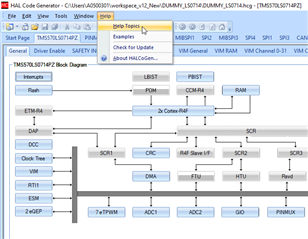
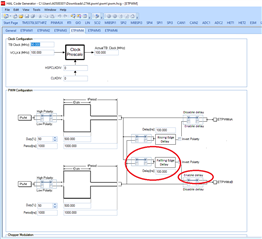
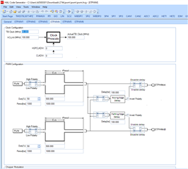
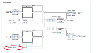
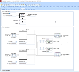
I want to generate a pwm signal (~60kHz) on the multiplexed pin 12 on TMS570LS0714APZ. This pin's default function is GIO.
I referred some articles to generate a variable duty cycle PWM using NHET module but found difficult as HET compiler should be used for that (please correct me if I'm wrong).
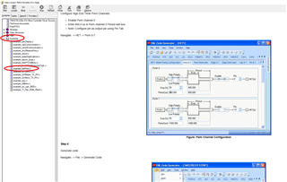
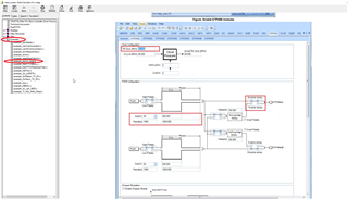
The other work around I believe is EPWM function on the pin. How can I achieve that?
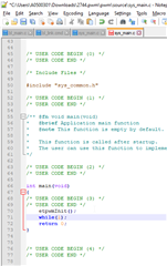
What are the steps required for that?
Please ask if you require any additional details.