I have modified the ssi_quad_mode example project to print 'Q' 'S' 'S' 'I' on SSI2. I receive the correct signal on three data lines, however it appears SSI2XDATA2 (pin PD7) does not output a signal. I have attached a snapshot of a scope capture of these lines:

DIO2 captures SSI2Clk, PD3
DIO1 captures SSI2XDATA3, PD6
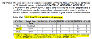
DIO0 captures SSI2DATAX2, PD7
DIO4 captures SSI2DATAX1, PD0
DIO3 captures SSI2DATAX0, PD1
I have ran a continuity test from my scope input to pin 42 on the X11 header on the evaluation board, and from my scope input to pin 128 on the MCU, both are fine. In addition, I have ran this code on another separate evaluation board and received the same results. Below, I have attach the code, keep in mind this was adapted from the ssi_quad_mode example project found in the TivaWare package:
#include <stdbool.h>
#include <stdint.h>
#include "inc/hw_memmap.h"
#include "inc/hw_ints.h"
#include "driverlib/debug.h"
#include "driverlib/gpio.h"
#include "driverlib/interrupt.h"
#include "driverlib/pin_map.h"
#include "driverlib/rom.h"
#include "driverlib/rom_map.h"
#include "driverlib/ssi.h"
#include "driverlib/sysctl.h"
#include "driverlib/uart.h"
#include "utils/uartstdio.h"

//****************************************************************************
//
// The variable g_ui32SysClock contains the system clock frequency in Hz.
//
//****************************************************************************
uint32_t g_ui32SysClock;

//*****************************************************************************
//
// Global flag to indicate data was received
//
//*****************************************************************************
volatile uint32_t g_bReceiveFlag = 0;

//*****************************************************************************
//
// Number of bytes to send and receive.
//
//*****************************************************************************
#define NUM_SSI_DATA            4

//*****************************************************************************
//
// The error routine that is called if the driver library encounters an error.
//
//*****************************************************************************
#ifdef DEBUG
void
__error__(char *pcFilename, uint32_t ui32Line)
{
}
#endif

//*****************************************************************************
//
// Configure the UART and its pins. This must be called before UARTprintf().
//
//*****************************************************************************
void
ConfigureUART(void)
{
    //
    // Enable the GPIO Peripheral used by the UART.
    //
    ROM_SysCtlPeripheralEnable(SYSCTL_PERIPH_GPIOA);

    //
    // Enable UART0.
    //
    ROM_SysCtlPeripheralEnable(SYSCTL_PERIPH_UART0);

    //
    // Configure GPIO Pins for UART mode.
    //
    ROM_GPIOPinConfigure(GPIO_PA0_U0RX);
    ROM_GPIOPinConfigure(GPIO_PA1_U0TX);
    ROM_GPIOPinTypeUART(GPIO_PORTA_BASE, GPIO_PIN_0 | GPIO_PIN_1);

    //
    // Initialize the UART for console I/O.
    //
    UARTStdioConfig(0, 115200, g_ui32SysClock);
}

//*****************************************************************************
//
// When the received FIFO is half-full, an interrupt will be generated.
//
//*****************************************************************************
//void
SSI1IntHandler(void)
{
    uint32_t ui32Status;

    //
    // Read the SSI Masked Interrupt Status.
    //
    ui32Status = MAP_SSIIntStatus(SSI2_BASE, true);

    //
    // Clear the SSI interrupt.
    //
    MAP_SSIIntClear(SSI2_BASE, ui32Status);

    //
    // Turn off the RX FIFO interrupt.
    //
    MAP_SSIIntDisable(SSI2_BASE, SSI_RXFF);

    //
    // Toggle flag to indicate that data has been received.
    //
    g_bReceiveFlag = 1;
}


//*****************************************************************************
//
// Configure SSI0 in Quad-SSI master Freescale (SPI) mode and SSI1 in Quad-SSI
// slave mode.  The SSI0 will send out 4 bytes of data in advanced Quad mode
// and the SSI1 slave will receive the 4 bytes of data also in Quad mode. The
// slave will generate interrupt upon receiving the 4 bytes of data.
//
//*****************************************************************************
int
main(void)
{
    uint32_t pui32DataTx[NUM_SSI_DATA];
    uint32_t pui32DataRx[NUM_SSI_DATA];
    uint32_t ui32Index;

    g_ui32SysClock = MAP_SysCtlClockFreqSet((SYSCTL_XTAL_25MHZ |
                                             SYSCTL_OSC_MAIN |
                                             SYSCTL_USE_PLL |
                                             SYSCTL_CFG_VCO_240), 120000000);

    //
    // Set up the serial console to use for displaying messages.
    //
    ConfigureUART();

    //
    // Display the setup on the console.
    //
    UARTprintf("SSI ->\n");
    UARTprintf("Mode: Advanced Quad-SPI\n");
    UARTprintf("Data: 8-bit\n\n");

    MAP_SysCtlPeripheralEnable(SYSCTL_PERIPH_SSI2);

    MAP_SysCtlPeripheralEnable(SYSCTL_PERIPH_GPIOD);

    UARTprintf("PERIPHERALS ENABLED\n");

    MAP_GPIOPinConfigure(GPIO_PD3_SSI2CLK);
    MAP_GPIOPinConfigure(GPIO_PD2_SSI2FSS);
    MAP_GPIOPinConfigure(GPIO_PD1_SSI2XDAT0);
    MAP_GPIOPinConfigure(GPIO_PD0_SSI2XDAT1);
    MAP_GPIOPinConfigure(GPIO_PD7_SSI2XDAT2);
    MAP_GPIOPinConfigure(GPIO_PD6_SSI2XDAT3);

    UARTprintf("GPIO CONFIGURED\n");

    MAP_GPIOPinTypeSSI(GPIO_PORTD_BASE, GPIO_PIN_7 | GPIO_PIN_6 | GPIO_PIN_3 |
                       GPIO_PIN_2 | GPIO_PIN_1 | GPIO_PIN_0);

    UARTprintf("GPIO PORTS SSI TYPE\n");

    MAP_SSIConfigSetExpClk(SSI2_BASE, g_ui32SysClock, SSI_FRF_MOTO_MODE_0,
                           SSI_MODE_MASTER, 2000000, 8);

    UARTprintf("SSI CLOCK CONFIGURED\n");

    MAP_SSIAdvModeSet(SSI2_BASE, SSI_ADV_MODE_QUAD_WRITE);

    UARTprintf("QSSI MODE SET\n");

    MAP_SSIAdvFrameHoldEnable(SSI2_BASE);

    UARTprintf("FRAME HOLD ENABLED\n");

    MAP_IntMasterEnable();

    UARTprintf("PROCESSOR ENABLE INTERRUPTS\n");

    MAP_SSIEnable(SSI2_BASE);

    UARTprintf("SSI ENABLED\n");

    while(MAP_SSIDataGetNonBlocking(SSI2_BASE, &pui32DataRx[0]))
    {
    }

    //
    // Initialize the data to send.
    //
    pui32DataTx[0] = 'Q';
    pui32DataTx[1] = 'S';
    pui32DataTx[2] = 'S';
    pui32DataTx[3] = 'I';

    //
    // Display indication that the SSI0 is transmitting data.
    //
    UARTprintf("SSI0 Sent:\n  ");
    UARTprintf("'Q' 'S' 'S' 'I' ");

    //
    // Send 4 bytes of data.
    //
    for(ui32Index = 0; ui32Index < NUM_SSI_DATA; ui32Index++)
    {
        //
        // Check if the last data byte is queued up to be sent.
        //
        if (ui32Index == (NUM_SSI_DATA - 1))
        {
            //
            // Calling SSIAdvDataPutFrameEnd on the last data will put out the
            // data and de-assert the the Fss pin.
            //
            MAP_SSIAdvDataPutFrameEnd(SSI2_BASE, pui32DataTx[ui32Index]);
        }
        else
        {
            //
            // Send the data using the "blocking" put function.  This function
            // will wait until there is room in the send FIFO before returning.
            // This allows you to assure that all the data you send makes it
            // into the send FIFO.
            //
            MAP_SSIDataPut(SSI2_BASE, pui32DataTx[ui32Index]);
        }
    }

    UARTprintf("\nSSI1 Received:\n  ");

    while (1);
}