This thread has been locked.

If you have a related question, please click the "Ask a related question" button in the top right corner. The newly created question will be automatically linked to this question.

TMS570LC4357: Compatibility mode SPI DMA hold CS active

Part Number: TMS570LC4357
Other Parts Discussed in Thread: HALCOGEN

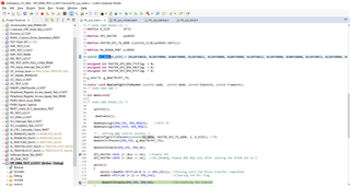
I am currently using SPI1 for some communications. The device I am talking to requires the CS to be held active (low) while I write a buffer. However, using DMA I seem to lose the ability to control the SPI CS hold. I had to modify the halcogen code slightly so can send a specific 3 bytes before I send the buffer each time and keep the CS active.

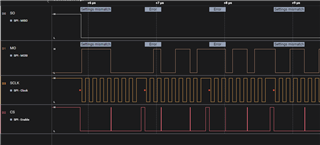
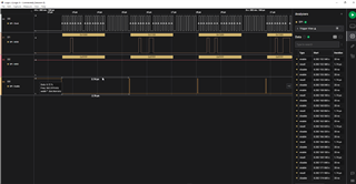
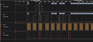
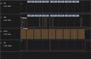
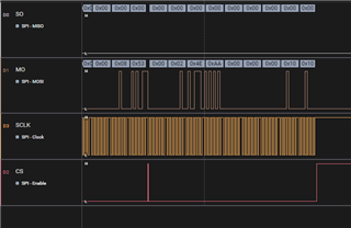
In the image below it shows the CS line toggling after each 8-bit transmission, which is what I want to prevent. Everything else seems to work okay. 

Simply I want the CS line to stay active low for the whole DMA transfer. So here are my questions:
1. Is there a way to use the SPI mode pin for CS along with DMA to control the CS to remain low for the entire block transfer? Or am I going to have to utilize a GIO pin instead?

2. Would switching to mibSPI be a better alternative? Does that provide more control of the CS pin with DMA?

  • Hi Spencer,

    For this requirement you can do one thing, instead of doing 8bit transfers from DMA you can do the 32 bit transfers from DMA  to the "SPIDAT1" register.

    Using this way you can get full control over the CSHOLD bit, that means you can decide what should be the CSHOLD bit value for each transfer from DMA.

    For example:

    In my recent thread one customer asked for 24bit transfer from SPI using DMA, actually 24 bit transfer will not possible directly from SPI as it supports max of 16bit transfer only.

    So what we did was we created a 32 bit transfers from DMA to SPIDATA1 register and in that transfer we made CSHOLD = 1 for first two times and on third time we made CSHOLD = 0 that means CS activate for every 3 byte transfer.

    If you verify above tx_data array there you can see the 28th bit (CS_HOLD) value in each data.

    As a result we got this kind of output:

    You can see CS line activated only after 24bit transfer and CS was in hold state for every 3 bytes.

    I am providing my code here, you can verify and modify for your requirement:

    3005.SPI_DMA_TEST_LC4357 (2).zip

    --
    Thanks & regards,
    Jagadish.

  • Thanks for the response. I am looking for something a little different than the solution you provided. The first 3 bytes are simply appended to the beginning of the buffer I need to send. Below is a capture of using SPI without DMA where I held CS low (The pulses on CS are just noise, not actually toggling). In this scenario I hold CS low for as long as I need.

  • I've made some progress in this. First I had a typo in copying over code from halcogen to start my SPI transfer and wasn't setting CS HOLD properly. After this I just had to make some logic to reset the CS HOLD which leads to the next point.

    In order to set CS hold inactive again, I set up an interrupt on the TX channel for LFS (Last Frame Start) and can set the CS HOLD bit in the SPI DAT1 registers. However, this is one frame too late (I am sending 1 element or 1 byte per frame, and frame count is the length of all the data I am sending). Because setting CS HOLD will only affect the following frame by setting the CS pin inactive after the next SPI tx. So currently, the DMA allows SPI to send 1 extra byte before setting the CS pin inactive which causes problems.

    So any extra knowledge to force the CS pin inactive using either the BTC or LFS interrupts would be helpful. I would prefer to avoid using the GIO functionality of the CS pin since SPI reads are still being done by the CPU and that utilizes the SPI functionality of all the pins.

    EDIT:
    This actually only seems to occur on the first SPI DMA transfer, the rest are okay somehow. The first picture below is what I want to achieve at the end of the SPI Transmit. The second picture is what I am getting (duplicated final byte as the CS is held low one extra transmission). Currently setting CS HOLD to inactive with the LFS interrupt.

  • If anyone has similar issues I solved my problem by using both SPI and GIO functionality in the end. I removed the LFS interrupt and only had the BTC interrupt in use.

    Before enabling DMA for SPI I set the CS pin to GIO function with PC0, and set it active (low) with PC3. Additionally I had to set CS_HOLD to 0 for SPI->DAT1.

    Once I got the BTC interrupt I only set the CS pin back to SPI function with PC0, specifically not setting it inactive again with PC3. This is because DMA will set the BTC flag before SPI is actually done so IF you manually reset CS with GIO it interrupts the final byte. But setting it back to SPI let's SPI reset CS, but note you specifically need to have the CS_HOLD bit set to 0 in the SPI->DAT1 register for the whole DMA. Otherwise SPI will just send one more duplicate byte.