This thread has been locked.

If you have a related question, please click the "Ask a related question" button in the top right corner. The newly created question will be automatically linked to this question.

TMS570LC4357: Analog to digital convertor

Part Number: TMS570LC4357
Other Parts Discussed in Thread: HALCOGEN

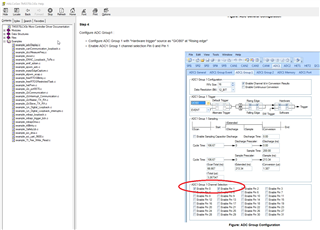
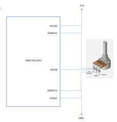
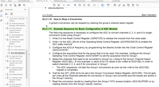
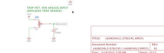
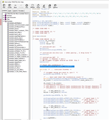
Iam  working  on  ADC  using  controller  tms570ls4357  , for that  i  need to give  analog input  to  channel  , what type of analog should be given , how its done ,  can u help me sir , from which register data will be stored . 

thank you ,

jeeva 

  • what  sir no reply 

    thank you

    jeeva

  • iam working on  ADC in controller tms570ls4357  using example code in halcogen  

    example_adcDisplay.c   for this  if  if  i will temperature sensor  output  to ADC0  will it  work  sir ,  any information related to this if u have please provide me sir
  • Hi Jeev,

    Apologies for the delay, i am on vacation for a week.

    In ADC example they are using ADC pin 0 and ADC pin 1.

    And they will be on W14 and V17 on the controller.

    --
    Thanks & regards,
    Jagadish.

  • dear sir  happy new year ,  for ADC  project   what type of analog signal shall i give  , example  any  external  sensor   should  i  connect  like  temperature sensor,  light sensor,  instead  of   any inbuilt  analog  provide  by  controller  TMS570LS4357   generate  analog signal and  give to analog pin  , will its possible sir

  • Happy New Year to you too.

    what type of analog signal shall i give  , example  any  external  sensor   should  i  connect  like  temperature sensor,  light sensor,  instead  of   any inbuilt  analog  provide  by  controller  TMS570LS4357   generate  analog signal and  give to analog pin

    For testing purpose, you can connect any DC supplies not only just sensors, but it's also just depending on your availability. The only thing is that your analog input should be within the range of ADREFLO to ADREFHI.

    You can also use variable DC supply sources like RPS (Regulated Power Supply) to test it.

    You can also use DAC of the controller, but this device doesn't have DAC, so you can use other controller DAC output to the ADC input of this device for testing.

    You can also use a potentiometer (a manually adjustable variable resistor), you can connect this resistor between ground and 3.3v supply and you can vary the resistance manually using knob of the potentiometer and you can give the output from the potentiometer to the input of the ADC. In this way you can just adjust the voltage between o to 3.3v and depends on the voltage ADC will generate the corresponding digital value.

    --
    Thanks & regards,
    Jagadish.

  •   dear   sir   in   ADREFLO to  ADREFHI   , ADREFLO  pin  should  be  connect  to  ground  and   ADREFHI  should  be  connected  into   3.3v  of  controller ,  then  later   if  i  consider  potentiometer  as  analog input  then  pin connect will done  as u said previous thread . , then  i will dump  example  code  is that fine  sir   

  • Hi Jeev,

    ADREFLO to  ADREFHI   , ADREFLO  pin  should  be  connect  to  ground  and   ADREFHI  should  be  connected  into   3.3v  of  controller ,  then  later   if  i  consider  potentiometer  as  analog input  then  pin connect will done  as u said previous thread . , then  i will dump  example  code  is that fine  sir   

    Yes, you are right.

    To understand more clearly follow the below connections.

    The input AD1IN pin should be your choice based on your application code. Once you dump the code and then adjust the potentiometer knob manually and you will get different ADC digital values based on applied input from the potentiometer.

    --
    Thanks & regards,
    Jagadish.

  • dear sir , instead of  using  example code  for ADC , shall i  able  to   generate  new  code  for ADC sir, without using using  inbuilt  function of  adc.c file its  possible sir . 

  • instead of  using  example code  for ADC , shall i  able  to   generate  new  code  for ADC sir, without using using  inbuilt  function of  adc.c file its  possible sir . 

    Yes, it is possible.

    Just carefully understand all the registers of ADC and then you can implement your own API for ADC conversion and reading.

  • dear sir , in controller TMS570LS4357  AD1IN_6  its have temperature sensor  using that shall i able to generate analog signal and give to ADC pin  will it convert and give me digital output sir

    thank you for fast reply

    jeeva

  • then only external  analog only can we can uses ,  if i generate  new code for ADC  using register like select register , status register ,  result register ,  enough sir other internal calculation of SAR  for that also we should get code sir , otherwise  if give analog signal  will its automatically generated  digital output 

    thank you

    jeeva

  • WHAT  SIR , NO REPLY FROM   U SIDE 

  • dear sir , in controller TMS570LS4357  AD1IN_6  its have temperature sensor  using that shall i able to generate analog signal and give to ADC pin  will it convert and give me digital output sir

    No, you can't do that. The internal temperature sensors of the controller can't produce an analog output on external pins. You can't do that.

    if i generate  new code for ADC  using register like select register , status register ,  result register ,  enough sir other internal calculation of SAR  for that also we should get code sir , otherwise  if give analog signal  will its automatically generated  digital output 

    There won't be any SAR configurations, please go through the TRM you can find everything you required.

    --
    Thanks & regards,
    Jagadish.

  • dear  sir i will follow steps what u provided  bt  result will be get hexa decimal , that i will convert into ASCII and i will display sir , between this only calculation is required sir , not  related SAR , once if we give analog signal is enough , no need to any extra calculation 

  • Hi Jeev,

    Actually, we already did this for Quadrature Encoder Example right?

    There i provided code to convert each hex bit into corresponding ASCII value and sent to the docklight through SCI right, use the same process.

    --
    Thanks & regards,
    Jagadish.

  • i no  need sir , i ask  if  follow  above  example sequence  which u mention   it  f enough   to convert  analog  to  digital  , that i asked  

  • dear sir  in controller TMS570LS4357  as  potentiometer  ADIN_6  for analog input  through that we cannot give analog to  ADC sir

  • IC U10  in controller  shall i use that one for analog signal

  • what  sir  no reply  for  last question

  • i ask  if  follow  above  example sequence  which u mention   it  f enough   to convert  analog  to  digital  , that i asked  

    Yes, follow the above-mentioned sequence. That is enough.

    dear sir  in controller TMS570LS4357  as  potentiometer  ADIN_6  for analog input  through that we cannot give analog to  ADC sir

    Yes, you can use this potentiometer.

    You no need to do any further connections here, as you can see potentiometer already connected to AD1IN[6], you just need to enable corresponding channel and do the conversion. If you want to change the analog input to the ADC then you just need to manually rotate the knob of the potentiometer, if you do that the analog input to the ADC will vary and so that you can also see the changes in the corresponding digital output as well.

    --
    Thanks & regards,
    Jagadish.

  • Dear  sir ,  i try  to  get ADC  through example code  of ADC  to know  what type of output  it will come , what value will   be  store in  register  after enable  the channel 6  for  Analog input  from potentiometer ,  but  it struct in adcisconvertcomplete() ,  not  moving  forward .  what will be issue sir , kindly reply fast sir

  • Hi Jeev,

    Please verify your code with "adcDisplay" example in HALCoGen, make sure you are following all the steps mentioned there. The code should work.

    --
    Thanks & regards,
    Jagadish.

  • Dear  sir  ,  same code nothing change  and  i followed   whatever they  mention in example code , and i enable  pin 6 channel of  ADCgroup1 . for analog input  of  potentiometer . 

  • dear  sir , we using  GIO  only  for hardware trigger , its means  in  Gio port i enable  direction pin ,that's all sir, 

  • Hi Jeev,

    I created a example project for your requirement:
    AD1IN_6_ADC_Display_Test_LC4357.zip

    I tested this project and it is working as expected.

    You can see the docklight data for channel-6 before adjusting potentiometer and i also captured by rotating potentiometer knob

    You can see after i rotating knob into anticlockwise, my digital output got reduced. I did this testing on my Launchpad board.

    Please compare your project with my project and do the necessary changes.

    --
    Thanks & regards,
    Jagadish.

  • thank you very much sir  its getting output , sir one doubt  yesterday u  have sent  one  example  sequence if we follow we will get same output sir 

  • Yes, you will get same output.

  • dear  sir default  reset control register is 0, if  i check value present in G1EMBUFFER = its giving 214789516  like its giving in operation control register is 40 in second array . if every are default by writing same thing what is use sir , is  they some other way

  • Select the channels that need to be converted in Group1 by writing to the Group1 Channel Select Register (ADG1SEL). In this example, a value of 0x115 needs to be written to ADG1SEL in order to select channels 0, 2, 4, and 8 for conversion in Group1

    Wait for the GP1_END bit to be set in the Group1 Conversion Status Register (ADG1SR). This bit gets set when all the channels selected for conversion in Group1 are converted and the results are stored in the Group1 memory.

    7. Read the conversion results by reading from the Group1 FIFO access location (ADG1BUFFER) or by reading directly from the Group1 results’ memory  

    sir  instruction is understood sir , due to that getting wrong  can explain that with example please sir 

  • i cannot understand  above instruction sir , getting confuse , can u explain  sir ,

    thank you

  • dear  sir ,  any  update 

  • ok sir ,  no  problem  i will  handle this one, thank you for ur support thank you

  • Hi Jeev,

    sir  instruction is understood sir , due to that getting wrong  can explain that with example please sir 

    You don't need any separate example to understand this, if you go through the example code carefully you can find all those steps in detail.

    As you can see, we are doing same steps in example code. Just go through their definition understand how they are using the registers.

    --
    Thanks & regards,
    Jagadish.

  • dear  sir  i understood  sir  , that  one  yesterday  while  debug the  code   itself  understood , now  that  is not  problem , from  railways  what signal will come  in that  which we  need  to  use ADC , about that i should work  using potentiometer is not  required esteems   sir ,  if i  search  online platform  its giving  pressure , temperature , audio etc . particular in  which things we need convert that  i know in  that so many thing , i will take care  if any help i required  i will text u sir , thank you for your  great support. thank you very much .

    jeeva

  • Dear  sir  in our  project from relay rack  we will get  analog signal and  given  to input card  through  we need to  convert Analog  to  digital signal   using  ADC, using    previous   example  code  we can achieve sir  

  • what  sir no reply, whether  is question is wrong

  • Hi Jeev,

    if i  search  online platform  its giving  pressure , temperature , audio etc

    You can use ADC for to interface with any sensor, the ADC conversion process is same for all the sensors. After getting digital output from ADC you will just reverse convert into the corresponding physical parameter value and will show in the user interface.

    Dear  sir  in our  project from relay rack  we will get  analog signal and  given  to input card  through  we need to  convert Analog  to  digital signal   using  ADC, using    previous   example  code  we can achieve sir  

    If you are interfacing with relays, which have only two states right? Relay ON and Relay OFF?

    If that is true then, you can use simple GIO's also to find the relay status. I mean if the relay output is 3.3v analog then relay might be OFF or 0v analog then relay might be ON, something like this. So in this case a simple GIO will give you High or Low status right?

    --
    Thanks & regards,
    Jagadish.

  • iam  not taking  about   normal  relay , i said  railway station they will use that relay

  • Hi Jeev,

    iam  not taking  about   normal  relay , i said  railway station they will use that relay

    I don't have any railway domain knowledge. I am just giving information about general relays. To know the status of relays we can just use GIO's instead of Analog inputs.

    You understood the working of the ADC right, it will just convert the 0 to 3.3 v into the 0x000 to 0xFFF. So, you can use it at anywhere where the signal is with in 0 to 3.3v and you can use that converted digital value to estimate the physical parameters.

    --
    Thanks & regards,
    Jagadish.

  • thank you  sir , if  any  it enough  sir ,  feature if i have doubt i  text to u , happy pongal sir 

    thank you,

    nanda kumar

  • Happy pongal to you too Jeeva.

  • dear sir ,  from  brake pressure  of  railway ,  using  pressure  sensor ,  that output i will give to controller   by converting   ampere  output   into  volt  output , range  is  between 0- 3.3v , how to convert  that  , can u help me sir 

  • Hi Jeev,

    Map your pressure sensor input with its output.

    For example, my pressure sensor will monitor the pressure in the range of 0 to 300bar. That means pressure sensor will give the 0v output to ADC for 0bar pressure and will give the 3.3v output to the ADC for 300bar pressure.

    I guess you already know how to convert the ADC digital result to the analog input right?

    Analog_value = (3.3 / 4096) * DigitalResult

    The above formula is for 12bit ADC and considering ADREFHI = 3.3v and ADREFLO = 0v.

    And after calculating analog value in your code for equivalent digital result and now you can convert the analog value into the pressure using below formula

    Pressure = (3.3 / 300) * Analog_value

    The above formula is so simple, the pressure sensor will give 3.3v for 300bar pressure right so in my code i got some analog value so that i am calculating the pressure for corresponding value.

    --
    Thanks & regards,
    Jagadish.

  • thank you for   your  reply sir ,  now  from   pressure   sensor   we  get  output is  4mA  to  20mA   that  one   we  cannot  connect to  microcontroller , for  that  we  need  to  convert into  voltage  form  , that  how  to  convert sir . before  giving  to  controller . can  u  exaplain sir 

  • Hi Jeev,

    ADC will sample the voltage and convert the voltage into the digital value right.

    You can 't give the current directly to ADC right, so you should convert the current to the voltage before applying to ADC. Add some resistance and convert the current to the voltage and after that follow the above conversion process i mentioned.

    And the process you are asking is not our scope Jeeva, we can only assist you in issues of our controller. We can verify the circuit you designed but you should design the circuit for your own.

    --
    Thanks & regards,
    Jagadish.

  • ok  sir  , thank you , i   wil  design  circuit   once design complete  i will verify  output  and   i  will inform u sir , thank you  for ur great support.  

  • dear sir ,  in our  project   from  pressure sensor  output  is  given  to  IC  LTC1992CMS8#PBF  then later  from  IC   to one more  IC  AMC1200BDWVR   then  output this IC  is  given  to microcontroller TMS570LS4357 .  i have one  doubt sir ,  LTC1992CMS8#PBF  from  this  IC  input  -IN and +IN  is  given  voltage  form  if its voltage means , from  sensor sensor we  get  current output , how  its  will be  work  , please  kindly  explain  this  both  IC  input and  output  form 

  • if u give  u r  opinion its  will really helpful for us 

  • Hi Jeev,

    Can you please raise a new thread for this issue, because this thread already becomes too long and if any one referring this thread might be confused.

    if u give  u r  opinion its  will really helpful for us 

    I will try to help you on this but the IC's you are talking here are new for me as well.

    So, i have to study them and understand before i can reply. So please expect some delay.

    --
    Thanks & regards,
    Jagadish.

  • ok  sir ,  tomorrow  if  will get  sir