This thread has been locked.

If you have a related question, please click the "Ask a related question" button in the top right corner. The newly created question will be automatically linked to this question.

TMS570LS3137-EP: flash ecc verification of the tms570ls3137

Part Number: TMS570LS3137-EP
Other Parts Discussed in Thread: UNIFLASH, TMS570LS3137

Hi Team,

There's an issue from the customer need your help:

First, I used uniflash to program the .out file into the flash of the chip. Uniflash has its own auto ecc generation function, which can automatically program the ecc area.

Then, I added to the startup code of my project

/* Enable CPU Event Export */
/* This allows the CPU to signal any single-bit or double-bit errors
detected
* by its ECC logic for accesses to program flash or data RAM.
*/
_coreEnableEventBusExport_();
/* USER CODE BEGIN (9) */
/* USER CODE END */

/* Enable response to ECC errors indicated by CPU for accesses to flash */
flashWREG->FEDACCTRL1 = 0x000A060AU;

/* USER CODE BEGIN (10) */
/* USER CODE END */

/* Enable CPU ECC checking for ATCM (flash accesses) */
_coreEnableFlashEcc_();

This should enable the chip's flash ecc verification.

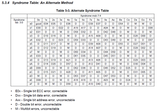
I want to verify the flash ecc check of the chip. I found that the flash of the chip comes with 7 diagnostic modes. I found the void checkFlashECC(void) function in the sys_selftest.c file. This function uses diagnostic mode 7 to automatically modify the ecc value read by the CPU to set single-bit and double-bit errors to verify the correctness of the flash ecc. 

But I found that in this function, after turning on diagnostic mode 7, the address accessed was not flash, but the mirrored image of flash was selected.

#define flashBadECC1 (*(volatile uint32 *)(0x20000000U))
#define flashBadECC2 (*(volatile uint32 *)(0x20000000U))

volatile uint32 flashread = 0U;
/* USER CODE BEGIN (40) */
/* USER CODE END */

/* Flash Module ECC Response enabled */
flashWREG->FEDACCTRL1 = 0x010A060AU;

/* Enable diagnostic mode and select diag mode 7 */
flashWREG->FDIAGCTRL = 0x00050007U;

/* Select ECC diagnostic mode, single-bit to be corrupted */
flashWREG->FPAROVR = 0x00005A01U;

/* Set the trigger for the diagnostic mode */
flashWREG->FDIAGCTRL |= 0x01000000U;

/* read a flash location from the mirrored memory map */
flashread = flashBadECC1;

/* disable diagnostic mode */
flashWREG->FDIAGCTRL = 0x000A0007U;

In this way, adding some debugging code to this function can reveal that single-bit errors and double-bit errors can change the value of the register flashWREG->FEDACSTATUS, that is, the CPU has detected an error.

However, when I changed the above flashBadECC1 flashBadECC2 to the flash area, I found that the value of the register flashWREG->FEDACSTATUS was still 0, that is, the CPU could not detect the error.

What's going on? Or is there any other way to check the function of flash ecc.

Thanks & Regards,

Ben

  • Hi Ben,

      Diagnostic mode 7 must be used in conjunction with a slave access access via Bus2 interface. The address 0x20000000 is a slave access to the flash via Bus2 interface. This is why flashBadECC1 is mapped to 0x20000000U which is a mirrored address to flash at 0x0. Please refer to the TRM for details. You cannot use the normal flash address between 0x0 and 3MB for diagnostic mode 7. 

      Also this week is a US holiday week. Please expect delay in response. 

    5.6.2.6 ECC Data Correction Diagnostic Mode 7: DIAGMODE = 7
    Testing the error correction and ECC logic in the CPU involves corrupting the ECC value returned to the
    CPU. By inverting one or more bits of the ECC, the CPU will detect errors in a selected data or ECC bit, or
    in any possible value returned by the ECC.
    To set an error for a particular bit use the syndrome, see Table 5-3. For instance if you want to corrupt
    data bit 62 then put the value 70h into the test register.
    The method uses the DATA_INV_PAR value in the FPAR_OVR register to alter the ECC during a slave
    access cycle. The value in the DATA_INV_PAR register will be XORed with the current ECC to give a bad
    ECC value to the CPU. This only will occur when the DIAG_MODE is 7, the PAR_OVR_KEY is 5, the
    DIAG_EN_KEY in the FDIAGCTRL register is 5 and the access is a slave cycle.
    This mode can set the FEDACSTATUS status error bits ECC_MUL_ERR or ERR_ZERO_FLG but it will
    not set D_UNC_ERR nor D_COR_ERR. Also the logic to support the ECCx_MAL_ERR and
    COMx_MAL_GOOD bits is not implemented for the CPU path so these bits will not set.
    The sequence to do this test would be:
    1. Make sure the true DMA module is off.
    2. Put 0101b into PAR_OVR_KEY and 101b into DAT_INV_PAR fields (00005Axxh) of the FPAR_OVR
    register (0x7C).
    3. Put the desired value in DAT_INV_PAR field of FPAR_OVR register.
    4. Put 7 in DIAG_MODE, and 5 in DIAG_EN_KEY of FDIAGCTRL (0x6C).
    5. Do a slave access of the desired address.
    6. Put 0 in DIAG_MODE or A in one of the key fields to turn off this test.
    7. Check error registers for ECC errors. (0x14, 0x1C, 0x20).
    8. Repeat as necessary to test out the ECC.
    9. Put 0 in DIAG_MODE and A in both of the key fields to completely disable this test at the end of the
    test.
    10. Write 5400h to FPAR_OVR(0x7C) to clear DAT_INV_PAR and put 2 into PAR_OVR_KEY.

  • Hi Charles,

    I found that the principle of ecc check code generation in the data sheet is not consistent with the principle of ordinary ecc check code generation. Is there any way for me to obtain the ecc check principle of the tms570ls3137 chip? For example, why are 19-bit address bits added? Why are the 7 bits of ecc0-ecc7 the XOR of the corresponding bit data? How to ensure that single-bit errors can be corrected and double-bit errors can be detected.

    Best Regards,

    Ben

  • For example, why are 19-bit address bits added?

    Hi,

      The ECC on TMS570LS3137 is not just based on the data but both the data the address. This will make sure if you read from a wrong address that happens to have the same data as the intended address will also fail the ECC check. Just as an example, let's say address 0x1000 has a value of 0x55555555 and address 0x1004 also has the same value 0x55555555 without the address included as part of the ECC generation, reading from 0x1000 would produce the same ECC as reading from 0x1004. What happens if there is a fault in the address generation that results in reading from 0x1004 (the incorrect address) as opposed to reading from the 0x1000 (the intended address)?

    Why are the 7 bits of ecc0-ecc7 the XOR of the corresponding bit data?

    This is to intentionally manipulate the ECC bits to cause the ECC logic to detect a fault. Normally, there is a ECC checksum for a corresponding data at a specific address location. The ECC logic will verify that the ECC checksum that is read along the data and address will match. How do you know if the ECC logic is doing its job to constantly verify the ECC checksum? What happens if the ECC logic is malfunction and never performs ECC check? This is why the ECC diagnostic mode 7 is used. It intentionally manipulate the ECC checksum to a value that is different from the expected value so that the ECC can detect it. This way you know the ECC logic is functioning. 

    Refer to the TRM for details. 

    5.6.2.6 ECC Data Correction Diagnostic Mode 7: DIAGMODE = 7
    Testing the error correction and ECC logic in the CPU involves corrupting the ECC value returned to the
    CPU. By inverting one or more bits of the ECC, the CPU will detect errors in a selected data or ECC bit, or
    in any possible value returned by the ECC.
    To set an error for a particular bit use the syndrome, see Table 5-3. For instance if you want to corrupt
    data bit 62 then put the value 70h into the test register.
    The method uses the DATA_INV_PAR value in the FPAR_OVR register to alter the ECC during a slave
    access cycle. The value in the DATA_INV_PAR register will be XORed with the current ECC to give a bad
    ECC value to the CPU. This only will occur when the DIAG_MODE is 7, the PAR_OVR_KEY is 5, the
    DIAG_EN_KEY in the FDIAGCTRL register is 5 and the access is a slave cycle.
    This mode can set the FEDACSTATUS status error bits ECC_MUL_ERR or ERR_ZERO_FLG but it will
    not set D_UNC_ERR nor D_COR_ERR. Also the logic to support the ECCx_MAL_ERR and
    COMx_MAL_GOOD bits is not implemented for the CPU path so these bits will not set.
    The sequence to do this test would be:
    1. Make sure the true DMA module is off.
    2. Put 0101b into PAR_OVR_KEY and 101b into DAT_INV_PAR fields (00005Axxh) of the FPAR_OVR
    register (0x7C).
    3. Put the desired value in DAT_INV_PAR field of FPAR_OVR register.
    4. Put 7 in DIAG_MODE, and 5 in DIAG_EN_KEY of FDIAGCTRL (0x6C).
    5. Do a slave access of the desired address.
    6. Put 0 in DIAG_MODE or A in one of the key fields to turn off this test.
    7. Check error registers for ECC errors. (0x14, 0x1C, 0x20).
    8. Repeat as necessary to test out the ECC.
    9. Put 0 in DIAG_MODE and A in both of the key fields to completely disable this test at the end of the
    test.
    10. Write 5400h to FPAR_OVR(0x7C) to clear DAT_INV_PAR and put 2 into PAR_OVR_KEY.