This thread has been locked.

If you have a related question, please click the "Ask a related question" button in the top right corner. The newly created question will be automatically linked to this question.

AM2434: RGMII2 of our custom board does not work properly.

Part Number: AM2434
Other Parts Discussed in Thread: SYSCONFIG
Hello! TI,

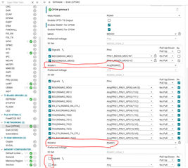
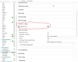
We are trying to use the CPSW example with RGMII2, but it does not work.
Using the example, we forcibly assigned an IP and checked Link Up and Network Up in the log.
However, no packets are received or transmitted.
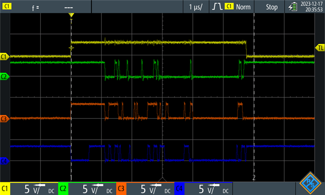
When we check the port sent from DP83869 to AM2434, we see the Rx signal and RXC signal, but there is no content in AM2434's UDMA memory for ENET.


Please help us.
 
 
  • Hi Seongyeol Yang,

    Can you please share some more details like

    1. What is the SDK version you are using,?

    2. What is the CPSW example you are trying to modify from the SDK?

    3. What exact modifications have you made to use the RGMII2?

    This will help me support you better.

    Regards,

    Shaunak

  • Dear TI.

    I am working with Seongyeol Yang.

    1. What is the SDK version you are using,?
    ->
    Tested with mcu_plus_sdk_am243x_08_06_00_48.
    I also tried mcu_plus_sdk_am243x_09_01_00_41 and it has the same symptom.


    2. What is the CPSW example you are trying to modify from the SDK?
    ->
    enet_cpsw_tcpserver_am243x-evm_r5fss0-0_freertos_ti-arm-clang
    enet_cpsw_loopback_am243x-evm_r5fss0-0_freertos_ti-arm-clang // only pass internal MAC test
    enet_cpsw_udpclient_am243x-evm_r5fss0-0_freertos_ti-arm-clang
    and
    I tried using the igss core and the symptoms were the same.


    3. What exact modifications have you made to use the RGMII2?
    ->
    load example and We removed unused parts from our custom board.
    Remove eeprom, io expander(i2c), DDR.
    use syscfg below.

    /**
     * These arguments were used when this file was generated. They will be automatically applied on subsequent loads
     * via the GUI or CLI. Run CLI with '--help' for additional information on how to override these arguments.
     * @cliArgs --device "AM243x_ALV_beta" --package "ALV" --part "ALV" --context "r5fss0-0" --product "MCU_PLUS_SDK_AM243x@09.01.00"
     * @versions {"tool":"1.18.1+3343"}
     */
    
    /**
     * Import the modules used in this configuration.
     */
    const gpio            = scripting.addModule("/drivers/gpio/gpio", {}, false);
    const gpio1           = gpio.addInstance();
    const i2c             = scripting.addModule("/drivers/i2c/i2c", {}, false);
    const i2c1            = i2c.addInstance();
    const i2c2            = i2c.addInstance();
    const clock           = scripting.addModule("/kernel/dpl/clock");
    const debug_log       = scripting.addModule("/kernel/dpl/debug_log");
    const mpu_armv7       = scripting.addModule("/kernel/dpl/mpu_armv7", {}, false);
    const mpu_armv71      = mpu_armv7.addInstance();
    const mpu_armv72      = mpu_armv7.addInstance();
    const mpu_armv73      = mpu_armv7.addInstance();
    const mpu_armv74      = mpu_armv7.addInstance();
    const mpu_armv75      = mpu_armv7.addInstance();
    const mpu_armv76      = mpu_armv7.addInstance();
    const default_linker  = scripting.addModule("/memory_configurator/default_linker", {}, false);
    const default_linker1 = default_linker.addInstance();
    const general         = scripting.addModule("/memory_configurator/general", {}, false);
    const general1        = general.addInstance();
    const region          = scripting.addModule("/memory_configurator/region", {}, false);
    const region1         = region.addInstance();
    const section         = scripting.addModule("/memory_configurator/section", {}, false);
    const section1        = section.addInstance();
    const section2        = section.addInstance();
    const section3        = section.addInstance();
    const section4        = section.addInstance();
    const section5        = section.addInstance();
    const section6        = section.addInstance();
    const section7        = section.addInstance();
    const section8        = section.addInstance();
    const section9        = section.addInstance();
    const enet_cpsw       = scripting.addModule("/networking/enet_cpsw/enet_cpsw", {}, false);
    const enet_cpsw1      = enet_cpsw.addInstance();
    
    /**
     * Write custom configuration values to the imported modules.
     */
    gpio1.$name                    = "CONFIG_GPIO0";
    gpio1.pinDir                   = "OUTPUT";
    gpio1.useMcuDomainPeripherals  = true;
    gpio1.MCU_GPIO.$assign         = "MCU_GPIO0";
    gpio1.MCU_GPIO.gpioPin.$assign = "MCU_SPI1_CS0";
    
    i2c1.$name           = "CONFIG_I2C0";
    i2c1.I2C.$assign     = "I2C0";
    i2c1.I2C.SCL.$assign = "I2C0_SCL";
    i2c1.I2C.SDA.$assign = "I2C0_SDA";
    
    i2c2.$name           = "CONFIG_I2C1";
    i2c2.I2C.$assign     = "I2C1";
    i2c2.I2C.SCL.$assign = "I2C1_SCL";
    i2c2.I2C.SDA.$assign = "I2C1_SDA";
    
    debug_log.enableUartLog = true;
    debug_log.enableCssLog  = false;
    debug_log.uartLog.$name = "CONFIG_UART0";
    
    const uart_v0_template  = scripting.addModule("/drivers/uart/v0/uart_v0_template", {}, false);
    const uart_v0_template1 = uart_v0_template.addInstance({}, false);
    uart_v0_template1.$name = "drivers_uart_v0_uart_v0_template0";
    debug_log.uartLog.child = uart_v0_template1;
    
    mpu_armv71.$name             = "CONFIG_MPU_REGION0";
    mpu_armv71.size              = 31;
    mpu_armv71.attributes        = "Device";
    mpu_armv71.accessPermissions = "Supervisor RD+WR, User RD";
    mpu_armv71.allowExecute      = false;
    
    mpu_armv72.$name             = "CONFIG_MPU_REGION1";
    mpu_armv72.size              = 15;
    mpu_armv72.accessPermissions = "Supervisor RD+WR, User RD";
    
    mpu_armv73.$name             = "CONFIG_MPU_REGION2";
    mpu_armv73.baseAddr          = 0x41010000;
    mpu_armv73.size              = 15;
    mpu_armv73.accessPermissions = "Supervisor RD+WR, User RD";
    
    mpu_armv74.$name             = "CONFIG_MPU_REGION3";
    mpu_armv74.accessPermissions = "Supervisor RD+WR, User RD";
    mpu_armv74.baseAddr          = 0x70000000;
    mpu_armv74.size              = 23;
    
    mpu_armv75.$name      = "CONFIG_MPU_REGION5";
    mpu_armv75.baseAddr   = 0xA5000000;
    mpu_armv75.size       = 23;
    mpu_armv75.attributes = "NonCached";
    
    mpu_armv76.$name    = "CONFIG_MPU_REGION6";
    mpu_armv76.baseAddr = 0x60000000;
    mpu_armv76.size     = 27;
    
    default_linker1.$name = "memory_configurator_default_linker0";
    
    general1.$name           = "CONFIG_GENERAL0";
    general1.heap_size       = 34000;
    general1.additional_data = "#include \"ti_enet_config.h\"";
    general1.stack_size      = 8192;
    general1.linker.$name    = "TIARMCLANG0";
    
    region1.$name                               = "MEMORY_REGION_CONFIGURATION0";
    region1.memory_region.create(5);
    region1.memory_region[0].type               = "TCMA_R5F";
    region1.memory_region[0].$name              = "R5F_VECS";
    region1.memory_region[0].size               = 0x40;
    region1.memory_region[0].auto               = false;
    region1.memory_region[1].type               = "TCMA_R5F";
    region1.memory_region[1].$name              = "R5F_TCMA";
    region1.memory_region[1].size               = 0x7FC0;
    region1.memory_region[2].type               = "TCMB_R5F";
    region1.memory_region[2].$name              = "R5F_TCMB0";
    region1.memory_region[2].size               = 0x8000;
    region1.memory_region[3].$name              = "MSRAM";
    region1.memory_region[3].auto               = false;
    region1.memory_region[3].manualStartAddress = 0x70080000;
    region1.memory_region[3].size               = 0x160000;
    region1.memory_region[4].type               = "FLASH";
    region1.memory_region[4].auto               = false;
    region1.memory_region[4].manualStartAddress = 0x60100000;
    region1.memory_region[4].size               = 0x100000;
    region1.memory_region[4].$name              = "FLASH";
    
    section1.$name                        = "Vector Table";
    section1.load_memory                  = "R5F_VECS";
    section1.group                        = false;
    section1.output_section.create(1);
    section1.output_section[0].$name      = ".vectors";
    section1.output_section[0].palignment = true;
    
    section2.$name                        = "Text Segments";
    section2.load_memory                  = "MSRAM";
    section2.output_section.create(5);
    section2.output_section[0].$name      = ".text.hwi";
    section2.output_section[0].palignment = true;
    section2.output_section[1].$name      = ".text.cache";
    section2.output_section[1].palignment = true;
    section2.output_section[2].$name      = ".text.mpu";
    section2.output_section[2].palignment = true;
    section2.output_section[3].$name      = ".text.boot";
    section2.output_section[3].palignment = true;
    section2.output_section[4].$name      = ".text:abort";
    section2.output_section[4].palignment = true;
    
    section3.$name                        = "Code and Read-Only Data";
    section3.load_memory                  = "MSRAM";
    section3.output_section.create(2);
    section3.output_section[0].$name      = ".text";
    section3.output_section[0].palignment = true;
    section3.output_section[1].$name      = ".rodata";
    section3.output_section[1].palignment = true;
    
    section4.$name                        = "Data Segment";
    section4.load_memory                  = "MSRAM";
    section4.output_section.create(1);
    section4.output_section[0].$name      = ".data";
    section4.output_section[0].palignment = true;
    
    section5.$name                        = "Memory Segments";
    section5.load_memory                  = "MSRAM";
    section5.output_section.create(2);
    section5.output_section[0].$name      = ".sysmem";
    section5.output_section[0].palignment = true;
    section5.output_section[1].$name      = ".stack";
    section5.output_section[1].palignment = true;
    
    section6.$name                                   = "CONFIG_SECTION2";
    section6.load_memory                             = "MSRAM";
    section6.output_section.create(1);
    section6.output_section[0].$name                 = ".bss";
    section6.output_section[0].palignment            = true;
    section6.output_section[0].output_sections_start = "__BSS_START";
    section6.output_section[0].output_sections_end   = "__BSS_END";
    
    section7.$name                                    = "Stack Segments";
    section7.load_memory                              = "MSRAM";
    section7.output_section.create(5);
    section7.output_section[0].$name                  = ".irqstack";
    section7.output_section[0].output_sections_start  = "__IRQ_STACK_START";
    section7.output_section[0].output_sections_end    = "__IRQ_STACK_END";
    section7.output_section[0].input_section.create(1);
    section7.output_section[0].input_section[0].$name = ". = . + __IRQ_STACK_SIZE;";
    section7.output_section[1].$name                  = ".fiqstack";
    section7.output_section[1].output_sections_start  = "__FIQ_STACK_START";
    section7.output_section[1].output_sections_end    = "__FIQ_STACK_END";
    section7.output_section[1].input_section.create(1);
    section7.output_section[1].input_section[0].$name = ". = . + __FIQ_STACK_SIZE;";
    section7.output_section[2].$name                  = ".svcstack";
    section7.output_section[2].output_sections_start  = "__SVC_STACK_START";
    section7.output_section[2].output_sections_end    = "__SVC_STACK_END";
    section7.output_section[2].input_section.create(1);
    section7.output_section[2].input_section[0].$name = ". = . + __SVC_STACK_SIZE;";
    section7.output_section[3].$name                  = ".abortstack";
    section7.output_section[3].output_sections_start  = "__ABORT_STACK_START";
    section7.output_section[3].output_sections_end    = "__ABORT_STACK_END";
    section7.output_section[3].input_section.create(1);
    section7.output_section[3].input_section[0].$name = ". = . + __ABORT_STACK_SIZE;";
    section7.output_section[4].$name                  = ".undefinedstack";
    section7.output_section[4].output_sections_start  = "__UNDEFINED_STACK_START";
    section7.output_section[4].output_sections_end    = "__UNDEFINED_STACK_END";
    section7.output_section[4].input_section.create(1);
    section7.output_section[4].input_section[0].$name = ". = . + __UNDEFINED_STACK_SIZE;";
    
    section8.$name                                              = "CONFIG_SECTION0";
    section8.group                                              = false;
    section8.type                                               = "NOLOAD";
    section8.load_memory                                        = "MSRAM";
    section8.output_section.create(1);
    section8.output_section[0].$name                            = ".enet_dma_mem ";
    section8.output_section[0].alignment                        = 128;
    section8.output_section[0].input_section.create(2);
    section8.output_section[0].input_section[0].$name           = "*(*ENET_DMA_DESC_MEMPOOL)";
    section8.output_section[0].input_section[1].$name           = "*(*ENET_DMA_RING_MEMPOOL)";
    section8.output_section[0].input_section[1].additional_data = "#if (ENET_SYSCFG_PKT_POOL_ENABLE == 1)\n        *(*ENET_DMA_PKT_MEMPOOL)\n#endif";
    
    section9.$name                       = "CONFIG_SECTION1";
    section9.load_memory                 = "MSRAM";
    section9.group                       = false;
    section9.type                        = "NOLOAD";
    section9.output_section.create(3);
    section9.output_section[0].$name     = "bss:ENET_DMA_OBJ_MEM";
    section9.output_section[0].alignment = 128;
    section9.output_section[1].$name     = ".bss:ENET_DMA_PKT_INFO_MEMPOOL";
    section9.output_section[1].alignment = 128;
    section9.output_section[2].$name     = ".bss:ENET_ICSSG_OCMC_MEM";
    section9.output_section[2].alignment = 128;
    
    enet_cpsw1.$name                        = "CONFIG_ENET_CPSW0";
    enet_cpsw1.PktInfoOnlyEnable            = true;
    enet_cpsw1.LargePoolPktCount            = 32;
    enet_cpsw1.customBoardEnable            = true;
    enet_cpsw1.mdioIPGRatio                 = 10;
    enet_cpsw1.DisableMacPort2              = true;
    enet_cpsw1.mdioMode                     = "MDIO_MODE_MANUAL";
    enet_cpsw1.txDmaChannel[0].$name        = "ENET_DMA_TX_CH0";
    enet_cpsw1.rxDmaChannel[0].$name        = "ENET_DMA_RX_CH0";
    enet_cpsw1.rxDmaChannel[0].macAddrCount = 2;
    enet_cpsw1.pinmux[0].$name              = "ENET_CPSW_PINMUX0";
    enet_cpsw1.pinmux[0].enableRgmii2       = false;
    enet_cpsw1.pinmux[0].MDIO.$assign       = "MDIO0";
    enet_cpsw1.pinmux[0].MDIO.MDC.$assign   = "PRG1_MDIO0_MDC";
    enet_cpsw1.pinmux[0].MDIO.MDIO.$assign  = "PRG1_MDIO0_MDIO";
    enet_cpsw1.pinmux[0].RGMII1.$assign     = "RGMII2";
    enet_cpsw1.netifInstance.create(1);
    enet_cpsw1.netifInstance[0].$name       = "NETIF_INST_ID0";
    
    const udma         = scripting.addModule("/drivers/udma/udma", {}, false);
    const udma1        = udma.addInstance({}, false);
    enet_cpsw1.udmaDrv = udma1;
    
    /**
     * Pinmux solution for unlocked pins/peripherals. This ensures that minor changes to the automatic solver in a future
     * version of the tool will not impact the pinmux you originally saw.  These lines can be completely deleted in order to
     * re-solve from scratch.
     */
    debug_log.uartLog.UART.$suggestSolution             = "USART0";
    debug_log.uartLog.UART.RXD.$suggestSolution         = "UART0_RXD";
    debug_log.uartLog.UART.TXD.$suggestSolution         = "UART0_TXD";
    enet_cpsw1.pinmux[0].RGMII1.RD0.$suggestSolution    = "PRG1_PRU1_GPO0";
    enet_cpsw1.pinmux[0].RGMII1.RD1.$suggestSolution    = "PRG1_PRU1_GPO1";
    enet_cpsw1.pinmux[0].RGMII1.RD2.$suggestSolution    = "PRG1_PRU1_GPO2";
    enet_cpsw1.pinmux[0].RGMII1.RD3.$suggestSolution    = "PRG1_PRU1_GPO3";
    enet_cpsw1.pinmux[0].RGMII1.RX_CTL.$suggestSolution = "PRG1_PRU1_GPO4";
    enet_cpsw1.pinmux[0].RGMII1.RXC.$suggestSolution    = "PRG1_PRU1_GPO6";
    enet_cpsw1.pinmux[0].RGMII1.TD0.$suggestSolution    = "PRG1_PRU1_GPO11";
    enet_cpsw1.pinmux[0].RGMII1.TD1.$suggestSolution    = "PRG1_PRU1_GPO12";
    enet_cpsw1.pinmux[0].RGMII1.TD2.$suggestSolution    = "PRG1_PRU1_GPO13";
    enet_cpsw1.pinmux[0].RGMII1.TD3.$suggestSolution    = "PRG1_PRU1_GPO14";
    enet_cpsw1.pinmux[0].RGMII1.TX_CTL.$suggestSolution = "PRG1_PRU1_GPO15";
    enet_cpsw1.pinmux[0].RGMII1.TXC.$suggestSolution    = "PRG1_PRU1_GPO16";
    

    Thanks.

  • Hi ,

    Thanks for sharing it.

    I will go through it once and get back with an update.

    Regards,

    Shaunak

  • Hi,

    If you could help me with answers to the following questions, I would be able to understand the issue better,

    1. Is your RGMII1 working fine with MAC port 1?

    From what I could understand from your sysconfig, MAC port 2 is disbaled and in pinmux config, "Enable RGMII2 for CPSW" is unchecked but pinmux is being done for RGMII2. 

    I would also recommend you to try and look at the sysconfig configurations of the enet_layer2_cpsw_switch example. It has the correct configuration for RGMII2.

    Can you please let me know if doing the syscfg changes according to the above suggested example works?

    Regards,
    Shaunak

  • Hi, 

    The example you provided can only be checked through the link-up.
    Our problem is that data cannot be sent or received after link up.

    We have a Q.
    Is there a partner for MAC Port Number and RGMII1 or RGMII2?
    Because Custom Board only has RGMII V2 port activated.
    When the same firmware is used for the EVM and Custom board, the EVM is assigned to MAC Port2 and the Custom board is assigned to MAC Port1.
    Could this cause a problem?

  • Dear TI.

    Log below

    Enabling clocks!
    EnetAppUtils_reduceCoreMacAllocation: Reduced Mac Address Allocation for CoreId:1 From 4 To 2
    Mdio_open: MDIO Manual_Mode enabled
    EnetPhy_bindDriver: PHY 0: OUI:080028 Model:0f Ver:01 <-> 'dp83869' : OK
    PHY 0 is alive
    Starting lwIP, local interface IP is dhcp-enabled
    [LWIPIF_LWIP] NETIF INIT SUCCESS
    Host MAC address-0 : f4:84:4c:f9:4d:29
    [0]Enet IF UP Event. Local interface IP:0.0.0.0
    [LWIPIF_LWIP] Enet has been started successfully
    [0]Waiting for network UP ...
    Cpsw_handleLinkUp: Port 1: Link up: 1-Gbps Full-Duplex
    MAC Port 1: link up // <- MAC Port 1 is right?
    [0]Network Link UP Event
    [0]Waiting for network UP ... // Doesn't Transfer data pkt
    [0]Waiting for network UP ... // Nothing happen 

  • Hi JungSik Shin and Seongyeol Yang

    I'll review it and get back to you with an update after some discussion with the team

    Regards,

    Shaunak

  • Hi,
     

    Is there a partner for MAC Port Number and RGMII1 or RGMII2?
    Because Custom Board only has RGMII V2 port activated.
    When the same firmware is used for the EVM and Custom board, the EVM is assigned to MAC Port2 and the Custom board is assigned to MAC Port1.

    Can you please elaborate this?

    Please note that RGMII2 pins are connected to MAC Port 2 and RGMII1 pins are connected to MAC Port 1. This cant be interchanged.
    If your PHY is connected to RGMII2, then you have to disable MAC Port 1 and keep MAC Port 2 only in syscfg-gui tool,

    Relevant screen shots of syscfg to configure MAC PORT2 only wit RGMII2


    Thanks and regards,

    Pradeep