This thread has been locked.

If you have a related question, please click the "Ask a related question" button in the top right corner. The newly created question will be automatically linked to this question.

AM2431: AM2431 connected to one switch IC setting problem

Part Number: AM2431
Other Parts Discussed in Thread: LP-AM243, SYSCONFIG

Hi all TI experts,

I am currently using a product board manufactured by our company, featuring the AM2431 as the main IC. Our board connects the AM2431 to a Realtek Ethernet switch IC via the RGMII interface. We are encountering issues in communicating with the switch IC.

I have previously tested the 'Enet Layer 2 CPSW Example' from the SDK on the LP-AM243 development board and successfully got it to work. However, the LP development board uses the CPSW3G to configure one host port and two MAC ports, connecting externally to two PHYs via MDIO/MDC. Our product board, on the other hand, connects only to a single switch IC, i.e., one PHY. Therefore, I believe it should be configured as CPSW2G, which means one host port and one MAC port. Additionally, my switch IC needs to be initialized through the MDIO/MDC interface. Here are my questions:

  1. In SysConfig, under Enet(CPSW) -> Pinmux config, since I am connecting to only one switch IC, I need only one PHY. Does this mean I should disable the signals for RGMII2 and retain only RGMII1?
  2. As I require only one MAC port, in SysConfig, under Enet(CPSW) -> MAC Port Config -> MAC Port2 Config, should I select 'Disable Mac Port 2'?
  3. According to the SDK documentation, specifically the 'Networking->Enet-LLD->Ethernet PHY Integration Guide' and 'Networking->Enet-LLD->Enet Migration Guide', I need to create a PHY driver for my switch IC at the corresponding address. I have also created my custom_board_config.c file, as I checked the option in SysConfig under Enet(CPSW)->Board Config. However, my PHY still fails to connect. My code is primarily a modification of the 'Enet Layer 2 CPSW Example'. The log stops after executing 'cpsw-3g: Waiting for link up...'. I suspect this might be due to my switch IC not undergoing the initialization process, as I don't see the program executing my written PHY driver. Even in debug mode, I couldn't see the program reaching that part, leaving me uncertain if there was a configuration error on my part.

Can someone guide me on what corrections I can make, or are there other documents I can refer to?

Best regards,

Larry

  • Hi Larry,

    Have you tried modifying the sysconfig settings to disable MAC port-2 and disable RGMII2 in pinmux?

    If you have tried it already and it still didnt work, can you please share your syscfg settings so we can clear our doubt about the issue being with the configuration.

    Else, can you please try disable them and try it once. 

    Regards,

    Shaunak

  • Hi Shaunak,

    Thanks for your reply, below is my syscfg file content,

    /**
     * These arguments were used when this file was generated. They will be automatically applied on subsequent loads
     * via the GUI or CLI. Run CLI with '--help' for additional information on how to override these arguments.
     * @cliArgs --device "AM243x_ALX_beta" --package "ALX" --part "ALX" --context "r5fss0-0" --product "MCU_PLUS_SDK_AM243x@09.00.00"
     * @versions {"tool":"1.17.0+3128"}
     */
    
    /**
     * Import the modules used in this configuration.
     */
    const eeprom          = scripting.addModule("/board/eeprom/eeprom", {}, false);
    const eeprom1         = eeprom.addInstance();
    const epwm            = scripting.addModule("/drivers/epwm/epwm", {}, false);
    const epwm1           = epwm.addInstance();
    const epwm2           = epwm.addInstance();
    const epwm3           = epwm.addInstance();
    const epwm4           = epwm.addInstance();
    const epwm5           = epwm.addInstance();
    const gpio            = scripting.addModule("/drivers/gpio/gpio", {}, false);
    const gpio1           = gpio.addInstance();
    const gpio2           = gpio.addInstance();
    const gpio3           = gpio.addInstance();
    const gpio4           = gpio.addInstance();
    const gpio5           = gpio.addInstance();
    const gpio6           = gpio.addInstance();
    const gpio7           = gpio.addInstance();
    const gpio8           = gpio.addInstance();
    const gpio9           = gpio.addInstance();
    const gpio10          = gpio.addInstance();
    const gpio11          = gpio.addInstance();
    const gpio12          = gpio.addInstance();
    const gpio13          = gpio.addInstance();
    const gpio14          = gpio.addInstance();
    const gpio15          = gpio.addInstance();
    const gpio16          = gpio.addInstance();
    const gpio17          = gpio.addInstance();
    const gpio18          = gpio.addInstance();
    const gpio19          = gpio.addInstance();
    const gpio20          = gpio.addInstance();
    const gpio21          = gpio.addInstance();
    const gpio22          = gpio.addInstance();
    const gpio23          = gpio.addInstance();
    const gpio24          = gpio.addInstance();
    const gpio25          = gpio.addInstance();
    const gpio26          = gpio.addInstance();
    const gpio27          = gpio.addInstance();
    const gpio28          = gpio.addInstance();
    const gpio29          = gpio.addInstance();
    const i2c             = scripting.addModule("/drivers/i2c/i2c", {}, false);
    const i2c1            = i2c.addInstance();
    const mcspi           = scripting.addModule("/drivers/mcspi/mcspi", {}, false);
    const mcspi1          = mcspi.addInstance();
    const pruicss         = scripting.addModule("/drivers/pruicss/pruicss", {}, false);
    const pruicss1        = pruicss.addInstance();
    const udma            = scripting.addModule("/drivers/udma/udma", {}, false);
    const udma1           = udma.addInstance();
    const addr_translate  = scripting.addModule("/kernel/dpl/addr_translate", {}, false);
    const addr_translate1 = addr_translate.addInstance();
    const clock           = scripting.addModule("/kernel/dpl/clock");
    const debug_log       = scripting.addModule("/kernel/dpl/debug_log");
    const mpu_armv7       = scripting.addModule("/kernel/dpl/mpu_armv7", {}, false);
    const mpu_armv71      = mpu_armv7.addInstance();
    const mpu_armv72      = mpu_armv7.addInstance();
    const mpu_armv73      = mpu_armv7.addInstance();
    const mpu_armv74      = mpu_armv7.addInstance();
    const mpu_armv75      = mpu_armv7.addInstance();
    const mpu_armv76      = mpu_armv7.addInstance();
    const enet_cpsw       = scripting.addModule("/networking/enet_cpsw/enet_cpsw", {}, false);
    const enet_cpsw1      = enet_cpsw.addInstance();
    
    /**
     * Write custom configuration values to the imported modules.
     */
    eeprom1.$name = "CONFIG_EEPROM0";
    
    epwm1.$name            = "ADD0";
    epwm1.EPWM.$assign     = "EHRPWM7";
    epwm1.EPWM.A.$assign   = "GPMC0_AD11";
    epwm1.EPWM.B.$used     = false;
    epwm1.EPWM.SYNCO.$used = false;
    epwm1.EPWM.SYNCI.rx    = false;
    epwm1.EPWM.SYNCI.$used = false;
    
    epwm2.$name            = "ADD1";
    epwm2.EPWM.$assign     = "EHRPWM3";
    epwm2.EPWM.A.$assign   = "GPMC0_AD13";
    epwm2.EPWM.B.$used     = false;
    epwm2.EPWM.SYNCO.$used = false;
    epwm2.EPWM.SYNCI.$used = false;
    
    epwm3.$name            = "ADD2";
    epwm3.EPWM.$assign     = "EHRPWM2";
    epwm3.EPWM.A.$assign   = "GPMC0_AD8";
    epwm3.EPWM.B.$used     = false;
    epwm3.EPWM.SYNCO.$used = false;
    epwm3.EPWM.SYNCI.$used = false;
    
    epwm4.$name            = "GCLK_GATE";
    epwm4.EPWM.$assign     = "EHRPWM0";
    epwm4.EPWM.A.$assign   = "GPMC0_AD3";
    epwm4.EPWM.B.$used     = false;
    epwm4.EPWM.SYNCO.$used = false;
    epwm4.EPWM.SYNCI.$used = false;
    
    epwm5.$name            = "GCLK_PWM";
    epwm5.EPWM.$assign     = "EHRPWM1";
    epwm5.EPWM.A.$assign   = "GPMC0_AD5";
    epwm5.EPWM.B.$used     = false;
    epwm5.EPWM.SYNCO.$used = false;
    epwm5.EPWM.SYNCI.$used = false;
    
    gpio1.$name                = "UDB1_L";
    gpio1.pinDir               = "OUTPUT";
    gpio1.GPIO.gpioPin.$assign = "PRG0_PRU0_GPO0";
    
    gpio2.$name                = "UDB2_L";
    gpio2.pinDir               = "OUTPUT";
    gpio2.GPIO.gpioPin.$assign = "PRG0_PRU0_GPO1";
    
    gpio3.$name                = "UDGI2_L";
    gpio3.GPIO.gpioPin.$assign = "PRG0_PRU0_GPO2";
    
    gpio4.$name                = "UDBI1_L";
    gpio4.GPIO.gpioPin.$assign = "PRG0_PRU0_GPO3";
    
    gpio5.$name                = "UDG2_L";
    gpio5.pinDir               = "OUTPUT";
    gpio5.GPIO.gpioPin.$assign = "PRG0_PRU0_GPO4";
    
    gpio6.$name                = "UDRI2_L";
    gpio6.GPIO.gpioPin.$assign = "PRG0_PRU0_GPO5";
    
    gpio7.$name                = "UDBI2_L";
    gpio7.GPIO.gpioPin.$assign = "PRG0_PRU0_GPO6";
    
    gpio8.$name                = "UDRI1_L";
    gpio8.GPIO.gpioPin.$assign = "PRG0_PRU0_GPO7";
    
    gpio9.$name                = "UDR2_L";
    gpio9.pinDir               = "OUTPUT";
    gpio9.GPIO.gpioPin.$assign = "PRG0_PRU0_GPO11";
    
    gpio10.$name                = "UDG1_L";
    gpio10.pinDir               = "OUTPUT";
    gpio10.GPIO.gpioPin.$assign = "PRG0_PRU0_GPO12";
    
    gpio11.$name                = "UDR1_L";
    gpio11.pinDir               = "OUTPUT";
    gpio11.GPIO.gpioPin.$assign = "PRG0_PRU0_GPO18";
    
    gpio12.$name                = "UDGI1_L";
    gpio12.GPIO.gpioPin.$assign = "PRG0_PRU0_GPO19";
    
    gpio13.$name                = "ULAT";
    gpio13.pinDir               = "OUTPUT";
    gpio13.GPIO.gpioPin.$assign = "PRG0_PRU1_GPO1";
    
    gpio14.$name                = "STATUS_R";
    gpio14.pinDir               = "OUTPUT";
    gpio14.GPIO.gpioPin.$assign = "PRG0_PRU1_GPO2";
    
    gpio15.$name                = "STATUS_G";
    gpio15.pinDir               = "OUTPUT";
    gpio15.GPIO.gpioPin.$assign = "PRG0_PRU1_GPO3";
    
    gpio16.$name                = "STATUS_B";
    gpio16.pinDir               = "OUTPUT";
    gpio16.GPIO.gpioPin.$assign = "PRG0_PRU1_GPO4";
    
    gpio17.$name                = "UDR2_R";
    gpio17.pinDir               = "OUTPUT";
    gpio17.GPIO.gpioPin.$assign = "PRG1_PRU0_GPO0";
    
    gpio18.$name                = "UDG1_R";
    gpio18.GPIO.gpioPin.$assign = "PRG1_PRU0_GPO1";
    
    gpio19.$name                = "UDB1_R";
    gpio19.pinDir               = "OUTPUT";
    gpio19.GPIO.gpioPin.$assign = "PRG1_PRU0_GPO2";
    
    gpio20.$name                = "UDRI2_R";
    gpio20.GPIO.gpioPin.$assign = "PRG1_PRU0_GPO3";
    
    gpio21.$name                = "UDRI1_R";
    gpio21.GPIO.gpioPin.$assign = "PRG1_PRU0_GPO4";
    
    gpio22.$name                = "UDR1_R";
    gpio22.GPIO.gpioPin.$assign = "PRG1_PRU0_GPO6";
    
    gpio23.$name                = "UDB2_R";
    gpio23.pinDir               = "OUTPUT";
    gpio23.GPIO.gpioPin.$assign = "PRG1_PRU0_GPO11";
    
    gpio24.$name                = "UDG2_R";
    gpio24.pinDir               = "OUTPUT";
    gpio24.GPIO.gpioPin.$assign = "PRG1_PRU0_GPO12";
    
    gpio25.$name                = "UDBI2_R";
    gpio25.GPIO.gpioPin.$assign = "PRG1_PRU0_GPO13";
    
    gpio26.$name                = "UDGI2_R";
    gpio26.GPIO.gpioPin.$assign = "PRG1_PRU0_GPO14";
    
    gpio27.$name                = "UDGI1_R";
    gpio27.GPIO.gpioPin.$assign = "PRG1_PRU0_GPO15";
    
    gpio28.$name                = "UDBI1_R";
    gpio28.GPIO.gpioPin.$assign = "PRG1_PRU0_GPO16";
    
    gpio29.$name                = "UDCLK";
    gpio29.pinDir               = "OUTPUT";
    gpio29.GPIO.gpioPin.$assign = "GPMC0_BE1n";
    
    i2c1.$name               = "CONFIG_I2C0";
    eeprom1.peripheralDriver = i2c1;
    i2c1.I2C.$assign         = "I2C0";
    
    mcspi1.$name                 = "SPI3";
    mcspi1.SPI.CLK.$assign       = "PRG0_PRU0_GPO16";
    mcspi1.SPI.D0.$assign        = "PRG0_PRU0_GPO13";
    mcspi1.SPI.D1.$assign        = "PRG0_PRU0_GPO14";
    mcspi1.mcspiChannel[0].$name = "CONFIG_MCSPI_CH0";
    
    pruicss1.$name                           = "CONFIG_PRU_ICSS0";
    pruicss1.AdditionalICSSSettings[0].$name = "CONFIG_PRU_ICSS_IO0";
    
    addr_translate1.$name = "CONFIG_ADDR_TRANSLATE_REGION0";
    
    clock.timerInputClkHz = 800000000;
    
    debug_log.enableUartLog            = true;
    debug_log.uartLog.$name            = "CONFIG_UART1";
    debug_log.uartLog.UART.$assign     = "USART0";
    debug_log.uartLog.UART.RXD.$assign = "UART0_RXD";
    debug_log.uartLog.UART.TXD.$assign = "UART0_TXD";
    
    mpu_armv71.$name             = "CONFIG_MPU_REGION0";
    mpu_armv71.size              = 31;
    mpu_armv71.attributes        = "Device";
    mpu_armv71.accessPermissions = "Supervisor RD+WR, User RD";
    mpu_armv71.allowExecute      = false;
    
    mpu_armv72.$name             = "CONFIG_MPU_REGION1";
    mpu_armv72.size              = 15;
    mpu_armv72.accessPermissions = "Supervisor RD+WR, User RD";
    
    mpu_armv73.$name             = "CONFIG_MPU_REGION2";
    mpu_armv73.baseAddr          = 0x41010000;
    mpu_armv73.size              = 15;
    mpu_armv73.accessPermissions = "Supervisor RD+WR, User RD";
    
    mpu_armv74.$name             = "CONFIG_MPU_REGION3";
    mpu_armv74.baseAddr          = 0x70000000;
    mpu_armv74.accessPermissions = "Supervisor RD+WR, User RD";
    mpu_armv74.size              = 23;
    
    mpu_armv75.$name             = "CONFIG_MPU_REGION5";
    mpu_armv75.baseAddr          = 0xA5000000;
    mpu_armv75.size              = 23;
    mpu_armv75.attributes        = "NonCached";
    mpu_armv75.accessPermissions = "Supervisor RD+WR, User RD";
    
    mpu_armv76.$name             = "CONFIG_MPU_REGION6";
    mpu_armv76.baseAddr          = 0x60000000;
    mpu_armv76.size              = 28;
    mpu_armv76.accessPermissions = "Supervisor RD, User RD";
    
    enet_cpsw1.$name                                     = "CONFIG_ENET_CPSW0";
    enet_cpsw1.mdioMode                                  = "MDIO_MODE_MANUAL";
    enet_cpsw1.DisableMacPort2                           = true;
    enet_cpsw1.customBoardEnable                         = true;
    enet_cpsw1.txDmaChannel[0].$name                     = "ENET_DMA_TX_CH0";
    enet_cpsw1.rxDmaChannel[0].$name                     = "ENET_DMA_RX_CH0";
    enet_cpsw1.pinmux[0].$name                           = "ENET_CPSW_PINMUX0";
    enet_cpsw1.pinmux[0].MDIO.$assign                    = "MDIO0";
    enet_cpsw1.pinmux[0].MDIO.MDC.$assignAllowConflicts  = "PRG1_MDIO0_MDC";
    enet_cpsw1.pinmux[0].MDIO.MDIO.$assignAllowConflicts = "PRG1_MDIO0_MDIO";
    enet_cpsw1.pinmux[0].RGMII1.$assign                  = "RGMII1";
    enet_cpsw1.pinmux[0].RGMII1.RD0.$assign              = "PRG1_PRU1_GPO5";
    enet_cpsw1.pinmux[0].RGMII1.RD1.$assign              = "PRG1_PRU1_GPO8";
    enet_cpsw1.pinmux[0].RGMII1.RD2.$assign              = "PRG1_PRU1_GPO18";
    enet_cpsw1.pinmux[0].RGMII1.RD3.$assign              = "PRG1_PRU1_GPO19";
    enet_cpsw1.pinmux[0].RGMII1.RX_CTL.$assign           = "PRG1_PRU0_GPO5";
    enet_cpsw1.pinmux[0].RGMII1.RXC.$assign              = "PRG1_PRU0_GPO8";
    enet_cpsw1.pinmux[0].RGMII1.TD0.$assign              = "PRG1_PRU1_GPO7";
    enet_cpsw1.pinmux[0].RGMII1.TD1.$assign              = "PRG1_PRU1_GPO9";
    enet_cpsw1.pinmux[0].RGMII1.TD2.$assign              = "PRG1_PRU1_GPO10";
    enet_cpsw1.pinmux[0].RGMII1.TD3.$assign              = "PRG1_PRU1_GPO17";
    enet_cpsw1.pinmux[0].RGMII1.TX_CTL.$assign           = "PRG1_PRU0_GPO9";
    enet_cpsw1.pinmux[0].RGMII1.TXC.$assign              = "PRG1_PRU0_GPO10";
    enet_cpsw1.pinmux[0].RGMII2.$assign                  = "RGMII2";
    enet_cpsw1.pinmux[0].RGMII2.RD0.$used                = false;
    enet_cpsw1.pinmux[0].RGMII2.RD1.$used                = false;
    enet_cpsw1.pinmux[0].RGMII2.RD2.$used                = false;
    enet_cpsw1.pinmux[0].RGMII2.RD3.$used                = false;
    enet_cpsw1.pinmux[0].RGMII2.RX_CTL.$used             = false;
    enet_cpsw1.pinmux[0].RGMII2.RXC.$used                = false;
    enet_cpsw1.pinmux[0].RGMII2.TD0.$used                = false;
    enet_cpsw1.pinmux[0].RGMII2.TD1.$used                = false;
    enet_cpsw1.pinmux[0].RGMII2.TD2.$used                = false;
    enet_cpsw1.pinmux[0].RGMII2.TD3.$used                = false;
    enet_cpsw1.pinmux[0].RGMII2.TX_CTL.$used             = false;
    enet_cpsw1.pinmux[0].RGMII2.TXC.$used                = false;
    
    udma1.$name        = "CONFIG_UDMA_PKTDMA_0";
    udma1.instance     = "PKTDMA_0";
    enet_cpsw1.udmaDrv = udma1;
    
    /**
     * Pinmux solution for unlocked pins/peripherals. This ensures that minor changes to the automatic solver in a future
     * version of the tool will not impact the pinmux you originally saw.  These lines can be completely deleted in order to
     * re-solve from scratch.
     */
    gpio1.GPIO.$suggestSolution                 = "GPIO1";
    gpio2.GPIO.$suggestSolution                 = "GPIO1";
    gpio3.GPIO.$suggestSolution                 = "GPIO1";
    gpio4.GPIO.$suggestSolution                 = "GPIO1";
    gpio5.GPIO.$suggestSolution                 = "GPIO1";
    gpio6.GPIO.$suggestSolution                 = "GPIO1";
    gpio7.GPIO.$suggestSolution                 = "GPIO1";
    gpio8.GPIO.$suggestSolution                 = "GPIO1";
    gpio9.GPIO.$suggestSolution                 = "GPIO1";
    gpio10.GPIO.$suggestSolution                = "GPIO1";
    gpio11.GPIO.$suggestSolution                = "GPIO1";
    gpio12.GPIO.$suggestSolution                = "GPIO1";
    gpio13.GPIO.$suggestSolution                = "GPIO1";
    gpio14.GPIO.$suggestSolution                = "GPIO1";
    gpio15.GPIO.$suggestSolution                = "GPIO1";
    gpio16.GPIO.$suggestSolution                = "GPIO1";
    gpio17.GPIO.$suggestSolution                = "GPIO0";
    gpio18.GPIO.$suggestSolution                = "GPIO0";
    gpio19.GPIO.$suggestSolution                = "GPIO0";
    gpio20.GPIO.$suggestSolution                = "GPIO0";
    gpio21.GPIO.$suggestSolution                = "GPIO0";
    gpio22.GPIO.$suggestSolution                = "GPIO0";
    gpio23.GPIO.$suggestSolution                = "GPIO0";
    gpio24.GPIO.$suggestSolution                = "GPIO0";
    gpio25.GPIO.$suggestSolution                = "GPIO0";
    gpio26.GPIO.$suggestSolution                = "GPIO0";
    gpio27.GPIO.$suggestSolution                = "GPIO0";
    gpio28.GPIO.$suggestSolution                = "GPIO0";
    gpio29.GPIO.$suggestSolution                = "GPIO0";
    i2c1.I2C.SCL.$suggestSolution               = "I2C0_SCL";
    i2c1.I2C.SDA.$suggestSolution               = "I2C0_SDA";
    mcspi1.SPI.$suggestSolution                 = "SPI3";
    mcspi1.mcspiChannel[0].CSn.$suggestSolution = "PRG0_PRU0_GPO17";
    

    Have you tried modifying the sysconfig settings to disable MAC port-2 and disable RGMII2 in pinmux?

      Yes, I have disabled MAC Port 2 and RGMII2 in the pinmux configuration. After making these changes, I attempted to run the program again, and the console displayed the following results:

    [MAIN_Cortex_R5_0_0] ==========================
         Layer 2 CPSW Test    
    ==========================
    
    Init all peripheral clocks
    ----------------------------------------------
    Enabling clocks!
    
    Create RX tasks
    ----------------------------------------------
    cpsw-3g: Create RX task
    
    Open all peripherals
    ----------------------------------------------
    cpsw-3g: Open enet
    EnetAppUtils_reduceCoreMacAllocation: Reduced Mac Address Allocation for CoreId:1 From 4 To 2 
    
    Init all configs
    ----------------------------------------------
    cpsw-3g: init config
    Mdio_open: MDIO Manual_Mode enabled
    
    cpsw-3g: Open port 1
    
    Attach core id 1 on all peripherals
    ----------------------------------------------
    cpsw-3g: Attach core
    cpsw-3g: Open DMA
    initQs() txFreePktInfoQ initialized with 16 pkts
    cpsw-3g: Waiting for link up...

    The program just stop at: waiting for link up......

    I have another issue. I followed the instructions in the SDK to create a new PHY driver, mimicking the contents of {SDK_folder}/source/networking/enet/core/src/phy/dp383822.c. However, in debug mode, I haven't observed the program execution reaching any part of this new driver. Since my driver requires initialization through MDIO/MDC, the lack of initialization could be one of the reasons the PHY isn't functioning. What could be the potential problem causing this issue?

    Best regard,

    Larry

  • Hi Larry,

    Would it be possible for you to share the MacPort and PHY register dumps to see what configurations we are using at run time. I will review your syscfg with the Enet Layer2 CPSW echo example, which has a similar configuration (only 1 port).

    Meanwhile, can you confirm if the new driver file that you are writing is getting compiled and linked to the main application as expected? Its odd that the new driver code is not being reached. 

    Regards,

    Shaunak

  • Hi Shaunak,

    Where can dump the  MacPort and PHY register?

    I can confirm that my PHY driver is being linked, as I attempted to disable the MDIO/MDC signals in the syscfg under 'Enet (CPSW) -> Pinmux config -> CPSW pinmux 0.' After running the program in this configuration, I observed that the program indeed reaches the PHY driver linked to the function pointer

    bool (*isPhyDevSupported)(EnetPhy_Handle hPhy, const EnetPhy_Version *version);.

    However, when I enable MDIO/MDC in CPSW pinmux 0, the program doesn't execute *isPhyDevSupported. It's really puzzling.

    Best regard,

    Larry

  • Hi Shaunak,

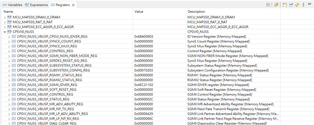
    Below is the CPSW0_NUSS register I found. Is this what you need?


    CPSW_NUSS_VBUSP_CPSW_NUSS_IDVER_REG	0x6BA00903	ID Version Register [Memory Mapped]	
    CPSW_NUSS_VBUSP_SYNCE_COUNT_REG	0x00000000	SyncE Count Register [Memory Mapped]	
    CPSW_NUSS_VBUSP_SYNCE_MUX_REG	0x00000000	SyncE Mux Register [Memory Mapped]	
    CPSW_NUSS_VBUSP_CONTROL_REG	0x00000000	Control Register [Memory Mapped]	
    CPSW_NUSS_VBUSP_SGMII_NON_FIBER_MODE_REG	0x00000003	SGMII NON FIBER Mode Register [Memory Mapped]	
    CPSW_NUSS_VBUSP_SERDES_RESET_ISO_REG	0x00000000	SyncE Mux Register [Memory Mapped]	
    CPSW_NUSS_VBUSP_SUBSSYSTEM_STATUS_REG	0x00000000	Subsystem Status Register [Memory Mapped]	
    CPSW_NUSS_VBUSP_SUBSYSTEM_CONFIG_REG	0x00070203	Subsystem Configuration Register [Memory Mapped]	
    CPSW_NUSS_VBUSP_RGMII1_STATUS_REG	0x00000000	RGMII1 Status Register [Memory Mapped]	
    CPSW_NUSS_VBUSP_RGMII2_STATUS_REG	0x00000000	RGMII2 Status Register [Memory Mapped]	
    CPSW_NUSS_VBUSP_SGMII_IDVER_REG	0x4EC21102	SGMII IDVER register [Memory Mapped]	
    CPSW_NUSS_VBUSP_SOFT_RESET_REG	0x00000000	SGMII Soft Reset Register [Memory Mapped]	
    CPSW_NUSS_VBUSP_CONTROL_REG	0x00000000	SGMII Control Register [Memory Mapped]	
    CPSW_NUSS_VBUSP_STATUS_REG	0x0000002C	SGMII Status Register [Memory Mapped]	
    CPSW_NUSS_VBUSP_MR_ADV_ABILITY_REG	0x00000000	SGMII MR Advertized Ability Register [Memory Mapped]	
    CPSW_NUSS_VBUSP_MR_NP_TX_REG	0x00000000	SGMII Next Pate Transmit Register [Memory Mapped]	
    CPSW_NUSS_VBUSP_MR_LP_ADV_ABILITY_REG	0x000064A9	SGMII Link Partner Advertized Ability Register [Memory Mapped]	
    CPSW_NUSS_VBUSP_MR_LP_NP_RX_REG	0x0000046C	SGMII Link Partner Next Page Receive Register [Memory Mapped]	
    CPSW_NUSS_VBUSP_DIAG_CLEAR_REG	0x00000000	SGMII Diagnostics Clear Register [Memory Mapped]	
    CPSW_NUSS_VBUSP_DIAG_CONTROL_REG	0x00000000	SGMII Diagnostics Control Register [Memory Mapped]	
    CPSW_NUSS_VBUSP_DIAG_STATUS_REG	0x00000509	SGMII Diagnostics Status Register [Memory Mapped]	
    CPSW_NUSS_VBUSP_MDIO_VERSION_REG	0x00070907	MDIO Version Register [Memory Mapped]	
    CPSW_NUSS_VBUSP_CONTROL_REG	0x810000FF	MDIO Control Register [Memory Mapped]	
    CPSW_NUSS_VBUSP_ALIVE_REG	0x00000000	MDIO Alive Register [Memory Mapped]	
    CPSW_NUSS_VBUSP_LINK_REG	0x00000000	MDIO Link Register [Memory Mapped]	
    CPSW_NUSS_VBUSP_LINK_INT_RAW_REG	0x00000000	MDIO Link Interrupt Raw Register [Memory Mapped]	
    CPSW_NUSS_VBUSP_LINK_INT_MASKED_REG	0x00000000	MDIO Link Interrupt Masked Register [Memory Mapped]	
    CPSW_NUSS_VBUSP_LINK_INT_MASK_SET_REG	0x00000000	MDIO Link Interrupt Mask Set Register [Memory Mapped]	
    CPSW_NUSS_VBUSP_LINK_INT_MASK_CLEAR_REG	0x00000000	MDIO Link Interrupt Mask Clear Register [Memory Mapped]	
    CPSW_NUSS_VBUSP_USER_INT_RAW_REG	0x00000000	MDIO User Interrupt Raw Register [Memory Mapped]	
    CPSW_NUSS_VBUSP_USER_INT_MASKED_REG	0x00000000	MDIO User Interrupt Masked Register [Memory Mapped]	
    CPSW_NUSS_VBUSP_USER_INT_MASK_SET_REG	0x00000000	MDIO User Interrupt Mask Set Register [Memory Mapped]	
    CPSW_NUSS_VBUSP_USER_INT_MASK_CLEAR_REG	0x00000000	MDIO User Interrupt Mask Clear Register [Memory Mapped]	
    CPSW_NUSS_VBUSP_MANUAL_IF_REG	0x00000005	MDIO Manual Interface  Register [Memory Mapped]	
    CPSW_NUSS_VBUSP_POLL_REG	0xC0000000	MDIO Poll Register [Memory Mapped]	
    CPSW_NUSS_VBUSP_POLL_EN_REG	0x80000000	MDIO Poll Enable Register [Memory Mapped]	
    CPSW_NUSS_VBUSP_CLAUS45_REG	0x00000000	MDIO Clause45 Register [Memory Mapped]	
    CPSW_NUSS_VBUSP_USER_ADDR0_REG	0x00000000	MDIO Address 0 Register [Memory Mapped]	
    CPSW_NUSS_VBUSP_USER_ADDR1_REG	0x00000000	MDIO Address 1 Register [Memory Mapped]	
    CPSW_NUSS_VBUSP_REVISION	0x6690A200	Revision Register [Memory Mapped]	
    CPSW_NUSS_VBUSP_eoi_reg	0x00000000	End of Interrupt Register [Memory Mapped]	
    CPSW_NUSS_VBUSP_intr_vector_reg	0x00000000	Interrupt Vector Register [Memory Mapped]	
    CPSW_NUSS_VBUSP_enable_reg_out_pulse_0	0x00000000	Enable Register 0 [Memory Mapped]	
    CPSW_NUSS_VBUSP_enable_clr_reg_out_pulse_0	0x00000000	Enable Clear Register 0 [Memory Mapped]	
    CPSW_NUSS_VBUSP_status_reg_out_pulse_0	0x00000000	Status Register 0 [Memory Mapped]	
    CPSW_NUSS_VBUSP_intr_vector_reg_out_pulse	0x00000000	Interrupt Vector for out_pulse [Memory Mapped]	
    CPSW_NUSS_VBUSP_CPSW_ID_VER_REG	0x6BA80903	CPSW ID Version [Memory Mapped]	
    CPSW_NUSS_VBUSP_CONTROL_REG	0x000EE004	CPSW Switch Control [Memory Mapped]	
    CPSW_NUSS_VBUSP_EM_CONTROL_REG	0x00000000	CPSW Emulation Control [Memory Mapped]	
    CPSW_NUSS_VBUSP_STAT_PORT_EN_REG	0x00000007	CPSW Statistics Port Enable [Memory Mapped]	
    CPSW_NUSS_VBUSP_PTYPE_REG	0x00000002	CPSW Transmit Priority Type [Memory Mapped]	
    CPSW_NUSS_VBUSP_SOFT_IDLE_REG	0x00000000	CPSW Software Idle [Memory Mapped]	
    CPSW_NUSS_VBUSP_THRU_RATE_REG	0x00003001	CPSW Thru Rate [Memory Mapped]	
    CPSW_NUSS_VBUSP_GAP_THRESH_REG	0x0000000B	CPSW Transmit FIFO Short Gap Threshold [Memory Mapped]	
    CPSW_NUSS_VBUSP_EEE_PRESCALE_REG	0x00000000	CPSW Energy Efficient Ethernet Prescale Value [Memory Mapped]	
    CPSW_NUSS_VBUSP_TX_G_OFLOW_THRESH_SET_REG	0xFFFFFFFF	CPSW PFC Tx Global Out Flow Threshold Set [Memory Mapped]	
    CPSW_NUSS_VBUSP_TX_G_OFLOW_THRESH_CLR_REG	0x00000000	CPSW PFC Tx Global Out Flow Threshold Clear [Memory Mapped]	
    CPSW_NUSS_VBUSP_TX_G_BUF_THRESH_SET_L_REG	0xFFFFFFFF	CPSW PFC Global Tx Buffer Threshold Set Low [Memory Mapped]	
    CPSW_NUSS_VBUSP_TX_G_BUF_THRESH_SET_H_REG	0xFFFFFFFF	CPSW PFC Global Tx Buffer Threshold Set High [Memory Mapped]	
    CPSW_NUSS_VBUSP_TX_G_BUF_THRESH_CLR_L_REG	0x00000000	CPSW PFC Global Tx Buffer Threshold Clear Low [Memory Mapped]	
    CPSW_NUSS_VBUSP_TX_G_BUF_THRESH_CLR_H_REG	0x00000000	CPSW PFC Global Tx Buffer Threshold Clear High [Memory Mapped]	
    CPSW_NUSS_VBUSP_VLAN_LTYPE_REG	0x88A88100	VLAN Length/type [Memory Mapped]	
    CPSW_NUSS_VBUSP_EST_TS_DOMAIN_REG	0x00000000	Enhanced Scheduled Traffic Host Event Domain [Memory Mapped]	
    CPSW_NUSS_VBUSP_CUT_THRESHOLD_REG	0x00000000	Cut-thru Threshold [Memory Mapped]	
    CPSW_NUSS_VBUSP_FREQUENCY_REG	0x00000140	CPSW CPPI_CLK Frequency in Mhz [Memory Mapped]	
    CPSW_NUSS_VBUSP_IET_HOLD_CNT_LD_VAL_REG	0x00000064	IET Hold Count Load Value [Memory Mapped]	
    CPSW_NUSS_VBUSP_TX_PRI0_MAXLEN_REG	0x000007E8	Transmit Priority 0 Maximum Length [Memory Mapped]	
    CPSW_NUSS_VBUSP_TX_PRI1_MAXLEN_REG	0x000007E8	Transmit Priority 1 Maximum Length [Memory Mapped]	
    CPSW_NUSS_VBUSP_TX_PRI2_MAXLEN_REG	0x000007E8	Transmit Priority 2 Maximum Length [Memory Mapped]	
    CPSW_NUSS_VBUSP_TX_PRI3_MAXLEN_REG	0x000007E8	Transmit Priority 3 Maximum Length [Memory Mapped]	
    CPSW_NUSS_VBUSP_TX_PRI4_MAXLEN_REG	0x000007E8	Transmit Priority 4 Maximum Length [Memory Mapped]	
    CPSW_NUSS_VBUSP_TX_PRI5_MAXLEN_REG	0x000007E8	Transmit Priority 5 Maximum Length [Memory Mapped]	
    CPSW_NUSS_VBUSP_TX_PRI6_MAXLEN_REG	0x000007E8	Transmit Priority 6 Maximum Length [Memory Mapped]	
    CPSW_NUSS_VBUSP_TX_PRI7_MAXLEN_REG	0x000007E8	Transmit Priority 7 Maximum Length [Memory Mapped]	
    

    I also discovered that my PHY driver is not bound, which seems to be caused by a specific segment of code in enetphy.c. At line 313, I noticed that my program, upon reaching this line, determines that MDC/MDIO is not alive, and therefore it does not enter the 'if' statement. As a result, the EnetPhy_blindDriver function is not executed, and thus my PHY driver is not being engaged. What could be the possible reasons for this?

    Best regards,

    Larry

  • Hi Larry,

    I'll review it and get back to you with an update.

    Regards,

    Shaunak

  • Hi Shaunak,

    Do you have any discovery into this issue? Looking forward to your reply.

    Best regards,

    Larry

  • Hi Larry,

    We are following up here: e2e.ti.com/.../4973192

  • Hi Shaunak,

    OK, thanks a lot for your help.

    Best regards,

    Larry