This thread has been locked.

If you have a related question, please click the "Ask a related question" button in the top right corner. The newly created question will be automatically linked to this question.

TM4C1294NCPDT: Sending a data from Board to PC

Part Number: TM4C1294NCPDT
Other Parts Discussed in Thread: EK-TM4C1294XL

Hi,

I want to develop application where the sampling rate of ADC must be 1MSPS and there are 4 channel to sample. I don't want to miss the data so I am using ethernet to send the data to my PC via TCP/IP protocol.

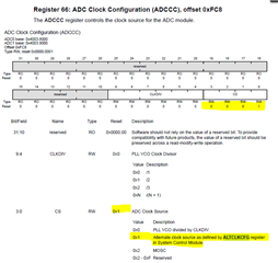
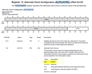
I went through enet_adcsensor_client_lwip example project, but I am not able to get configure ADC conversion speed as 1MSPS.

Requesting you to please guide.

thanks.

  • Hi,

      By default, the ADC uses PIOSC (16Mhz) as the clock source to derive the ADCCLK. Since PIOSC is 16Mhz, the maximum ADCCLK can only be 16Mhz. You should be able to get 1MSPS with 16Mhz ADCCLK.

    See below description. ADC clock source is by default derived from ALTCLKCFG. The ALTCLKCFG by default is PIOSC. 

    15.3.2.7 Module Clocking
    The ADC digital block is clocked by the system clock and the ADC analog block is clocked from a
    separate conversion clock (ADC Clock). The ADC clock frequency can be up to 32 MHz to generate
    a conversion rate of 2 Msps. A 16 MHz ADC clock provides a 1 Msps sampling rate. There are three
    sources of the ADC clock:
    Divided PLL VCO. The PLL VCO frequency can be configured to generate up to a 32-MHz clock
    for a conversion rate of 2 Msps. The CS field in the ADCCC register must be programmed to
    0x0 to select the PLL VCO and the CLKDIV field is used to set the appropriate clock divisor for
    the desired frequency.

    ■ 16 MHz PIOSC. Using the PIOSC provides a conversion rate near 1 Msps. To use the PIOSC
    to clock the ADC, first power up the PLL and then enable the PIOSC in the CS bit field in the
    ADCCC register, then disable the PLL.
    ■ MOSC. The MOSC clock source must be 16 MHz for a 1 Msps conversion rate and 32 MHz for
    a 2 Msps conversion rate.
    The system clock must be at the same frequency or higher than the ADC clock. All ADC modules
    share the same clock source to facilitate the synchronization of data samples between conversion
    units, the selection and programming of which is provided by ADC0's ADCCC register. The ADC
    modules do not run at different conversion rates.

    To achieve higher sample rate such as 2MSPS, you will need to derive the ADCCLK from the PLL VCO. In this case, you can configure ADCCLK for 32Mhz. Refer to this post with sample code provided by Bob.

    https://e2e.ti.com/support/microcontrollers/arm-based-microcontrollers-group/arm-based-microcontrollers/f/arm-based-microcontrollers-forum/690227/ccs-ek-tm4c1294xl-adc-not-running-at-2msps-capped-at-1msps/2545036#2545036


  • I run bob's code, and it is running fine. But there is some confusion what I see is in Bob's reply ->

    Sorry, there is an issue with the documentation. The ADC converter clock is really PLL VCO divided by 2, then divided by the value in the CLKDIV field (CLKDIV+1)  of the ADCCC register. You cannot get 32MHz ADC clock running the PLL VCO at 480MHz, but running the PLL VCO at 320MHz, you can get 2MSPS by using divide by 5.

    The issue is further complicated by the fact that at 2MSPS there is not enough time to use TivaWare calls in the interrupt service routine to toggle a GPIO pin and clear the interrupt. (Much less, read and store the sample.) In the example below I replaced some TivaWare calls with direct register writes to avoid the overhead of the subroutine calls.

    But in my application I want send the data to my laptop while using the TCP/IP protocol. But as per Bob's reply, we cannot use tivaware library to process and send the data.

    Is there any solution available? because I don't want to miss any data while converting the ADC at 1 MHz of frequency and send it over ethernet.

    Thanks.

  • Hi,

      What Bob means is that at 2MSPS, you will not have enough time to process the ADC data in the interrupt before the next sample is taken. If it is 2MSPS, then there are a maximum of120Mhz/2Mhz=60 cycles. When you receive an ADC interrupt, there is first some latency from the time an interrupt is generated until the CPU enters the ISR. Inside the ISR, you will need to read and clear the ADC status plus reading the ADC data or whatever tasks you want to do. In Bob's case, he was trying to toggle a GPIO pin. All of these operations take cycles. While these operations are being executed inside the ISR, perhaps another ADC sample arrives and the interrupt is generated again before you even exit out of the current ADC ISR. I think you can resolve this by slowing down the sample rate to 1MSPS instead of 2MSPS plus using uDMA to transfer the ADC data instead of using CPU. 

      Refer to this example at C:\ti\TivaWare_C_Series-2.2.0.295\examples\boards\ek-tm4c1294xl\adc_udma_pingpong on how to use uDMA in ping-pong mode to transfer ADC data to temporary buffers. I will suggest you run this example as is to get a feel for using the uDMA before you add code to transfer the data from the buffer to Ethernet. 

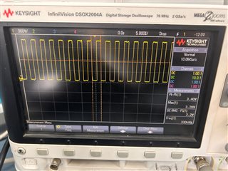
  •  When i running a following code to sample a ADC data at 1Msps, I am able to watch only 333.38Khz of frequency on GPIO E port. but if I am correct then i should get the value 1Mhz/64 = 15625Hz right?

    Am I missing something?

    //*****************************************************************************
    
    #include <stdbool.h>
    #include <stdint.h>
    #include "inc/hw_ints.h"
    #include "inc/hw_memmap.h"
    #include "inc/hw_adc.h"
    #include "inc/hw_types.h"
    #include "inc/hw_udma.h"
    #include "driverlib/adc.h"
    #include "driverlib/debug.h"
    #include "driverlib/gpio.h"
    #include "driverlib/interrupt.h"
    #include "driverlib/pin_map.h"
    #include "driverlib/rom.h"
    #include "driverlib/rom_map.h"
    #include "driverlib/sysctl.h"
    #include "driverlib/systick.h"
    #include "driverlib/timer.h"
    #include "driverlib/uart.h"
    #include "driverlib/udma.h"
    #include "utils/uartstdio.h"
    
    
    //*****************************************************************************
    //
    // The variable g_ui32SysClock contains the system clock frequency in Hz.
    //
    //*****************************************************************************
    uint32_t g_ui32SysClock;
    
    //*****************************************************************************
    //
    // Definition for ADC buffer size.
    //
    //*****************************************************************************
    #define ADC_SAMPLE_BUF_SIZE     256
    
    //*****************************************************************************
    //
    // The control table used by the uDMA controller.  This table must be aligned
    // to a 1024 byte boundary.
    //
    //*****************************************************************************
    #if defined(ewarm)
    #pragma data_alignment=1024
    uint8_t pui8ControlTable[1024];
    #elif defined(ccs)
    #pragma DATA_ALIGN(pui8ControlTable, 1024)
    uint8_t pui8ControlTable[1024];
    #else
    uint8_t pui8ControlTable[1024] __attribute__ ((aligned(1024)));
    #endif
    
    //*****************************************************************************
    //
    // Global buffers to store ADC sample data.
    //
    //*****************************************************************************
    static uint16_t pui16ADCBuffer1[ADC_SAMPLE_BUF_SIZE];
    static uint16_t pui16ADCBuffer2[ADC_SAMPLE_BUF_SIZE];
    
    //*****************************************************************************
    //
    // Each possible state of the fill status for an ADC buffer.
    //
    //*****************************************************************************
    enum BUFFER_STATUS
    {
        EMPTY,
        FILLING,
        FULL
    };
    
    //*****************************************************************************
    //
    // Global variable to keep track of the fill status of each ADC buffer.
    //
    //*****************************************************************************
    static enum BUFFER_STATUS pui32BufferStatus[2];
    
    //*****************************************************************************
    //
    // The count of uDMA errors.  This value is incremented by the uDMA error
    // handler.
    //
    //*****************************************************************************
    static uint32_t g_ui32DMAErrCount = 0u;
    
    //*****************************************************************************
    //
    // The error routine that is called if the driver library encounters an error.
    //
    //*****************************************************************************
    #ifdef DEBUG
    void
    __error__(char *pcFilename, uint32_t ui32Line)
    {
    }
    #endif
    
    //*****************************************************************************
    //
    // The interrupt handler for uDMA errors.  This interrupt will occur if the
    // uDMA encounters a bus error while trying to perform a transfer.  This
    // handler just increments a counter if an error occurs.
    //
    //*****************************************************************************
    void
    uDMAErrorHandler(void)
    {
        uint32_t ui32Status;
    
        //
        // Check for uDMA error bit.
        //
        ui32Status = uDMAErrorStatusGet();
    
        //
        // If there is a uDMA error, then clear the error and increment
        // the error counter.
        //
        if(ui32Status)
        {
            uDMAErrorStatusClear();
            g_ui32DMAErrCount++;
        }
    }
    uint16_t g_flagAdc0 = 0;
    //*****************************************************************************
    //
    // Interrupt handler for ADC0 Sequence Zero.
    //
    //*****************************************************************************
    void
    ADCSeq0Handler(void)
    {
    
        GPIOPinWrite(GPIO_PORTE_BASE, GPIO_PIN_0, GPIOPinRead(GPIO_PORTE_BASE, GPIO_PIN_0)^ (GPIO_PIN_0));
    
     //GPIOPinWrite(GPIO_PORTE_BASE, GPIO_PIN_0, GPIO_PIN_0);
    
        //
        // Clear the Interrupt Flag.
        //
        ADCIntClear(ADC0_BASE, 0);


        //
        // Determine which buffer as been filled based on the UDMA_MODE_STOP flag
        // and update the buffer status.
        //
        if ((uDMAChannelModeGet(UDMA_CHANNEL_ADC0 | UDMA_PRI_SELECT) ==
                                UDMA_MODE_STOP) &&
                               (pui32BufferStatus[0] == FILLING))
        {
            pui32BufferStatus[0] = FULL;
            pui32BufferStatus[1] = FILLING;
        }
        else if ((uDMAChannelModeGet(UDMA_CHANNEL_ADC0 | UDMA_ALT_SELECT) ==
                                     UDMA_MODE_STOP) &&
                                    (pui32BufferStatus[1] == FILLING))
        {
            pui32BufferStatus[0] = FILLING;
            pui32BufferStatus[1] = FULL;
        }
    }
    
    //*****************************************************************************
    //
    // Configure the UART and its pins.  This must be called before UARTprintf().
    //
    //*****************************************************************************
    void
    ConfigureUART(void)
    {
        //
        // Enable the GPIO Peripheral used by the UART.
        //
        MAP_SysCtlPeripheralEnable(SYSCTL_PERIPH_GPIOA);
    
        //
        // Enable UART0.
        //
        MAP_SysCtlPeripheralEnable(SYSCTL_PERIPH_UART0);
    
        //
        // Configure GPIO Pins for UART mode.
        //
        MAP_GPIOPinConfigure(GPIO_PA0_U0RX);
        MAP_GPIOPinConfigure(GPIO_PA1_U0TX);
        MAP_GPIOPinTypeUART(GPIO_PORTA_BASE, GPIO_PIN_0 | GPIO_PIN_1);
    
        //
        // Initialize the UART for console I/O.
        //
        UARTStdioConfig(0, 115200, g_ui32SysClock);
    }
    
    //*****************************************************************************
    //
    // This example demonstrates how to use the uDMA controller to transfer data
    // between the ADC peripheral and memory buffers.  It also uses a timer to
    // trigger ADC measurements at a 16 kHz sampling frequency.
    //
    //*****************************************************************************
    int
    main(void)
    {
        uint32_t ui32Count, ui32AverageResult1, ui32AverageResult2;
        uint32_t ui32SamplesTaken = 0;
    
        //
        // Run from the PLL at 120 MHz.
        // Note: SYSCTL_CFG_VCO_240 is a new setting provided in TivaWare 2.2.x and
        // later to better reflect the actual VCO speed due to SYSCTL#22.
        //
        g_ui32SysClock = SysCtlClockFreqSet((SYSCTL_XTAL_25MHZ |
                                             SYSCTL_OSC_MAIN |
                                             SYSCTL_USE_PLL |
                                             SYSCTL_CFG_VCO_240), 120000000);
    
        //
        // Initialize the buffer status.
        //
        pui32BufferStatus[0] = FILLING;
        pui32BufferStatus[1] = EMPTY;
    
        //
        // Enable the peripherals used by this application.
        //
        MAP_SysCtlPeripheralEnable(SYSCTL_PERIPH_ADC0);
        MAP_SysCtlPeripheralEnable(SYSCTL_PERIPH_UDMA);
        MAP_SysCtlPeripheralEnable(SYSCTL_PERIPH_TIMER0);
        MAP_SysCtlPeripheralEnable(SYSCTL_PERIPH_GPIOE);
    
        //
        // Enable the GPIO pin for ADC0 Channel 0 (PE3) which configures it for
        // analog functionality.
        //
        MAP_GPIOPinTypeADC(GPIO_PORTE_BASE, GPIO_PIN_3);
        GPIOPinTypeGPIOOutput(GPIO_PORTE_BASE, GPIO_PIN_0);
        //
        // Initialize UART0 and write initial status.
        //
        ConfigureUART();
        UARTprintf("Timer->ADC->uDMA demo!\n\n");
        UARTprintf("ui32AverageResult1\tui32AverageResult2\tTotal Samples\n");
    
        //
        // Enable the uDMA controller.
        //
        uDMAEnable();
    
        //
        // Point at the control table to use for channel control structures.
        //
        uDMAControlBaseSet(pui8ControlTable);
    
        //
        // Put the attributes in a known state for the uDMA ADC0 channel.  These
        // should already be disabled by default.
        //
        uDMAChannelAttributeDisable(UDMA_CHANNEL_ADC0,
                                    UDMA_ATTR_ALTSELECT | UDMA_ATTR_HIGH_PRIORITY |
                                    UDMA_ATTR_REQMASK);
    
        //
        // Configure the control parameters for the primary control structure for
        // the ADC0 channel.  The primary control structure is used for the "A"
        // part of the ping-pong receive.  The transfer data size is 16 bits, the
        // source address does not increment since it will be reading from a
        // register.  The destination address increment is 16-bits.  The
        // arbitration size is set to one byte transfers.
        //
        uDMAChannelControlSet(UDMA_CHANNEL_ADC0 | UDMA_PRI_SELECT, UDMA_SIZE_16 |
                              UDMA_SRC_INC_NONE | UDMA_DST_INC_16 | UDMA_ARB_1);
    
        //
        // Configure the control parameters for the alternate control structure for
        // the ADC0 channel.  The alternate control structure is used for the
        // "B" part of the ping-pong receive.  The configuration is identical to
        // the primary/A control structure.
        //
        uDMAChannelControlSet(UDMA_CHANNEL_ADC0 | UDMA_ALT_SELECT, UDMA_SIZE_16 |
                              UDMA_SRC_INC_NONE | UDMA_DST_INC_16 | UDMA_ARB_1);
    
        //
        // Set up the transfer parameters for the ADC0 primary control structure
        // The mode is set to ping-pong, the transfer source is the ADC Sample
        // Sequence Result FIFO 0 register, and the destination is the receive
        // "A" buffer.  The transfer size is set to match the size of the buffer.
        //
        uDMAChannelTransferSet(UDMA_CHANNEL_ADC0 | UDMA_PRI_SELECT,
                               UDMA_MODE_PINGPONG,
                               (void *)(ADC0_BASE + ADC_O_SSFIFO0),
                               &pui16ADCBuffer1, ADC_SAMPLE_BUF_SIZE);
    
        //
        // Set up the transfer parameters for the ADC0 primary control structure
        // The mode is set to ping-pong, the transfer source is the ADC Sample
        // Sequence Result FIFO 0 register, and the destination is the receive
        // "B" buffer.  The transfer size is set to match the size of the buffer.
        //
        uDMAChannelTransferSet(UDMA_CHANNEL_ADC0 | UDMA_ALT_SELECT,
                               UDMA_MODE_PINGPONG,
                               (void *)(ADC0_BASE + ADC_O_SSFIFO0),
                               &pui16ADCBuffer2, ADC_SAMPLE_BUF_SIZE);
    
        //
        // Set the USEBURST attribute for the uDMA ADC0 channel.  This will force
        // the controller to always use a burst when transferring data from the
        // TX buffer to the UART.  This is somewhat more efficient bus usage than
        // the default which allows single or burst transfers.
        //
        uDMAChannelAttributeEnable(UDMA_CHANNEL_ADC0, UDMA_ATTR_USEBURST);
    
    
        // Enables DMA channel so it can perform transfers.  As soon as the
        // channels are enabled, the peripheral will issue a transfer request and
        // the data transfers will begin.
        //
        uDMAChannelEnable(UDMA_CHANNEL_ADC0);
    
        //
        // Use ADC0 sequence 0 to sample channel 0 once for each timer period.
        //
        ADCClockConfigSet(ADC0_BASE, ADC_CLOCK_SRC_PLL | ADC_CLOCK_RATE_FULL, 8);
    
        //
        // Wait for the clock configuration to set.
        //
        SysCtlDelay(10);
    
        //
        // Disable the ADC0 sequence 0 interrupt on the processor (NVIC).
        //
        IntDisable(INT_ADC0SS0);
    
        //
        // Disable interrupts for ADC0 sample sequence 0 to configure it.
        //
        ADCIntDisable(ADC0_BASE, 0);
    
        //
        // Disable ADC0 sample sequence 0.  With the sequence disabled, it is now
        // safe to load the new configuration parameters.
        //
        ADCSequenceDisable(ADC0_BASE, 0);
    
        //
        // Enable sample sequence 0 with a processor signal trigger.  Sequence 0
        // will do a single sample when the processor sends a signal to start the
        // conversion.
        //
        ADCSequenceConfigure(ADC0_BASE, 0, ADC_TRIGGER_TIMER, 0);
    
        //
        // Configure step 0 on sequence 0.  Sample channel 0 (ADC_CTL_CH0) in
        // single-ended mode (default) and configure the interrupt flag
        // (ADC_CTL_IE) to be set when the sample is done.  Tell the ADC logic
        // that this is the last conversion on sequence 0 (ADC_CTL_END).  Sequence
        // 0 has 8 programmable steps.  Since we are only doing a single conversion
        // using sequence 0 we will only configure step 0.  For more information
        // on the ADC sequences and steps, reference the datasheet.
        //
        ADCSequenceStepConfigure(ADC0_BASE, 0, 0, ADC_CTL_CH0 | ADC_CTL_END |
                                 ADC_CTL_IE);
    
        //
        // Since sample sequence 0 is now configured, it must be enabled.
        //
        ADCSequenceEnable(ADC0_BASE, 0);
    
        //
        // Clear the interrupt status flag.  This is done to make sure the
        // interrupt flag is cleared before we sample.
        //
        ADCIntClear(ADC0_BASE, 0);
    
        //
        // Enables the DMA channel for the ADC0 sample sequence 0.
        //
        ADCSequenceDMAEnable(ADC0_BASE, 0);
    
        //
        // Enable the ADC 0 sample sequence 0 interrupt.
        //
        ADCIntEnable(ADC0_BASE, 0);
    
        //
        // Enable the interrupt for ADC0 sequence 0 on the processor (NVIC).
        //
        IntEnable(INT_ADC0SS0);
    
        //
        // Configure a 16-bit periodic timer.
        //
        TimerConfigure(TIMER0_BASE, TIMER_CFG_SPLIT_PAIR | TIMER_CFG_A_PERIODIC);
    
        //
        // Set ADC sampling frequency to be 1MHz i.e. every 1uS.
        //
        TimerLoadSet(TIMER0_BASE, TIMER_A, (g_ui32SysClock/1000000) - 1);
    
        //
        // Enable the ADC trigger output for Timer A.
        //
        TimerControlTrigger(TIMER0_BASE, TIMER_A, true);
    
        //
        // Enable processor interrupts.
        //
        IntMasterEnable();
    
        //
        // Enable Timer 0 which will start the whole application process.
        //
        TimerEnable(TIMER0_BASE, TIMER_A);
    
        while(1)
        {
    
     //        //
            // Check if the first buffer is full, if so process data.
            //
            if(pui32BufferStatus[0] == FULL)
            {
                //
                // Process the data in pui16ADCBuffer1 and clear buffer entries.
                //
                ui32AverageResult1 = 0;
    
                for(ui32Count = 0; ui32Count < ADC_SAMPLE_BUF_SIZE; ui32Count++)
                {
                    ui32AverageResult1 += pui16ADCBuffer1[ui32Count];
                    pui16ADCBuffer1[ui32Count] = 0;
                }
    
                pui32BufferStatus[0] = EMPTY;
    
                //
                // Enable for another uDMA block transfer.
                //
                uDMAChannelTransferSet(UDMA_CHANNEL_ADC0 | UDMA_PRI_SELECT,
                                       UDMA_MODE_PINGPONG,
                                       (void *)(ADC0_BASE + ADC_O_SSFIFO0),
                                       &pui16ADCBuffer1, ADC_SAMPLE_BUF_SIZE);
                //
                // Enable DMA channel so it can perform transfers.
                //
                uDMAChannelEnable(UDMA_CHANNEL_ADC0 | UDMA_PRI_SELECT);
    
                //
                // Track the number of samples taken and update the average.
                //
       //          ui32SamplesTaken += ADC_SAMPLE_BUF_SIZE;
        //         ui32AverageResult1 = ((ui32AverageResult1 +
         //                             (ADC_SAMPLE_BUF_SIZE / 2)) /
         //                              ADC_SAMPLE_BUF_SIZE);
            }
    
            //
            // Check if the second buffer is full, if so process data.
            //
            if(pui32BufferStatus[1] == FULL)
            {
                //
                // Process the data in pui16ADCBuffer2 and clear buffer entries.
                //
                ui32AverageResult2 = 0;
    
                for(ui32Count =0; ui32Count < ADC_SAMPLE_BUF_SIZE; ui32Count++)
                {
                    ui32AverageResult2 += pui16ADCBuffer2[ui32Count];
                    pui16ADCBuffer2[ui32Count] = 0;
                }
    
                //
                // Indicate the Buffer data as been processed so new data can
                // be stored.
                //
                pui32BufferStatus[1] = EMPTY;
    
                //
                // Enable for another uDMA block transfer.
                //
                uDMAChannelTransferSet(UDMA_CHANNEL_ADC0 | UDMA_ALT_SELECT,
                                       UDMA_MODE_PINGPONG,
                                       (void *)(ADC0_BASE + ADC_O_SSFIFO0),
                                       &pui16ADCBuffer2, ADC_SAMPLE_BUF_SIZE);
    
                //
                // Enable DMA channel so it can perform transfers.
                //
                uDMAChannelEnable(UDMA_CHANNEL_ADC0 | UDMA_ALT_SELECT);
    
                //
                // Track the number of samples taken and update the average.
                //
    //            ui32SamplesTaken += ADC_SAMPLE_BUF_SIZE;
    //            ui32AverageResult2 = ((ui32AverageResult2 +
        //                              (ADC_SAMPLE_BUF_SIZE / 2)) /
          //                             ADC_SAMPLE_BUF_SIZE);
    
                //
                // Both buffers have been filled by now, so print out the two
                // average results and the number of samples taken so far.
                //
                //UARTprintf("\t%4d\t\t\t%4d\t\t%d\r", ui32AverageResult1,
                           //ui32AverageResult2, ui32SamplesTaken);
    
    
            }
    //        GPIOPinWrite(GPIO_PORTE_BASE, GPIO_PIN_0, 0);
        }
    }


  • i should get the value 1Mhz/64 = 15625Hz right?

    Where is the 64 coming from? Why 1Mhz? Your VCO is 240Mhz and in your  below call, you are dividing the VCO by 8 which will give you 30Mhz for the ADCCLK. This is defining the ADCCLK clock speed at which it will convert the input data. 

    ADCClockConfigSet(ADC0_BASE, ADC_CLOCK_SRC_PLL | ADC_CLOCK_RATE_FULL, 8);

    Your below call defines the rate at which you will sample the input. Every 1uS, the timer sends a trigger to the ADC to convert an input. 

    //
    // Set ADC sampling frequency to be 1MHz i.e. every 1uS.
    //
    TimerLoadSet(TIMER0_BASE, TIMER_A, (g_ui32SysClock/1000000) - 1);

  • Thanks, Charles, for your suggestion. I made changes as per your feedback.

    Now, I have intergrated the adc_ping_pong logic with TCP/IP client code. For testing my code i am using Hercules 3.2.8 . But whnever I am receiving the data my hercules got crashed. As per my knowledge i am sending the data too quickly. Is there any way to send the data once my pcBuf full? 

    // Check if the first buffer is full, if so process data.
    //
    if(pui32BufferStatus[0] == FULL)
    {


    //
    // Process the data in pui16ADCBuffer1 and clear buffer entries.
    //
    for(ui32Count =0; ui32Count < sizeof(pui16ADCBuffer1) / sizeof(pui16ADCBuffer1[0]); ui32Count++)

    {

    sprintf(pcBuf ,"Data[%d] : %d\n",ui32Count,pui16ADCBuffer1);
    TcpSendPacket(pcBuf);

    pui16ADCBuffer2[ui32Count] = 0;
    }

    Ethernet payload is around 1500 byte. but I am sending <5 byte. So is there any way to increase the size of frame. Attaching you the full code.

    enet_adcsensor_client_lwip.zip

  • I think your problem is very likely due to the fact that you are calling lwIP API not in the context of the Ethernet Interrupt handler. Refer to David Wilson's comments in the below post which will be very useful. 

    https://e2e.ti.com/support/microcontrollers/arm-based-microcontrollers-group/arm-based-microcontrollers/f/arm-based-microcontrollers-forum/319674/optimizing-udp-in-lwip-on-tiva---how-to-determine-when-a-packet-has-been-sent

    "The biggest problem here is the fact that you are calling lwIP from a context other than the Ethernet interrupt handler. lwIP is not re-entrant so you must only call it from one context. When using an RTOS, this means only calling the lwIP APIs from a single thread. When not using an RTOS (like most of our examples), you must make calls in the context of the Ethernet interrupt handler. This can be tricky to do but there's a timer callback implemented that makes it a bit easier. Make sure you set HOST_TMR_INTERVAL to some non-zero value (I think it's a number of milliseconds) and implement lwIPHostTimerHandler in your application then make all your lwIP calls from the lwIPHostTimerHandler function.

    This may sound awkward but it's vital. Calling udp_send from the main loop will likely work for a while but I guarantee you that it will crash after some period of time as some internal data structure in lwIP gets corrupted. This kind of problem is VERY difficult to debug so it's far better to fix this now rather than trying to pretend everything is OK and have it fail catastrophically later."

  • Hi @Tsai

    Thank you for suggesting me to write TcpPacketSend into the lwipHostTimerhandler, Now I am getting countinuous data for a longer timer. 
    But While sending the data to server some times error pops up like ERROR: Code: -1 (TcpSendPacket :: tcp_write), also i am checking the out at server side on hercules terminal. But terminal also getting crashed while receiving the data .please help me for the same.

  • Hi,

      I will suggest you turn on the debug info to investigate the cause of the problem. See below snippet to update the debug logging in lwipopts.h file. 

    //*****************************************************************************
    //
    // ---------- Debugging options ----------
    //
    //*****************************************************************************
    #if 1
    #define U8_F "c"
    #define S8_F "c"
    #define X8_F "x"
    #define U16_F "u"
    #define S16_F "d"
    #define X16_F "x"
    #define U32_F "u"
    #define S32_F "d"
    #define X32_F "x"
    extern void UARTprintf(const char *pcString, ...);
    #define LWIP_PLATFORM_DIAG(msg) UARTprintf msg
    #define LWIP_PLATFORM_ASSERT(msg) \
    UARTprintf("ASSERT_FAIL at line %d of %s:\ %s\n", __LINE__, __FILE__, msg)
    #define LWIP_DEBUG 1
    #endif