Part Number: MSP432E401Y
Other Parts Discussed in Thread: TRSF3243, TRS232, MSP-EXP432E401Y
Hi,
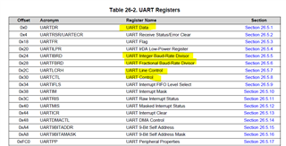
I have an MSP432E401Y based product that I need to modify to implement an RS-232 interface. Looking through the data sheet for the MSP432E401Y I was able to find the appropriate pins to use and where the UART registers are located in memory, but there are a lot of details about implementing RS-232 that are still not clear to me.
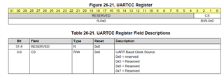
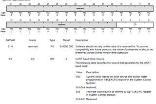
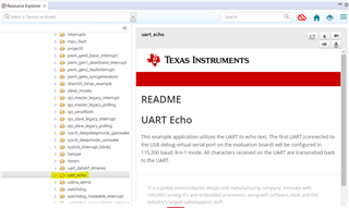
Just a few issues I still don't know how to do include how to set the baud rate, how to send a byte of data, where an incoming byte of data will be located, the polarity of incoming and outgoing data, etc.
Can someone explain these issues to me, or is there a document available that explains them? I don't see any of it in the data sheet I have.
Thank you.