This thread has been locked.

If you have a related question, please click the "Ask a related question" button in the top right corner. The newly created question will be automatically linked to this question.

MSPM0G3507: MCAN SDK example is not working.

Part Number: MSPM0G3507
Other Parts Discussed in Thread: SYSCONFIG

Hi Team,

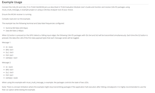
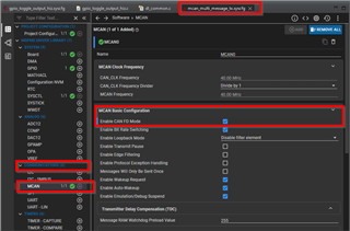
I am trying to use the CAN-FD module on MSPM0Gx device with the SDK example - mcan_multi_message_tx. Below is my setup-

1. Using LP-MSPM0G3507 for this example.

2. Probing the CAN_Tx pin (PA12) over the scope. 

3. When I flash the example and press the S2 switch to initiate the transfer, it doesn't show up on the scope. 

Please let me know if I am missing something here or any other information is needed.

Regards,

Sai.

  • Hi Sai,

    You should be able to see at least the first transaction attempt in your setup. Try setting a trigger and capturing that first one after an initial programming or a full POR.

    In order to send/receive multiple commands you would have to follow the hardware setup described in the readme for this project and the one from mcan_message_rx. With both sender and receiver connected you will be able to see multiple commands. 

    Best Regards,
    Brandon Fisher

  • Hii sir ,

    1)can we use  high speed CAN instead of CAN FD and what changes we have to do in sysconfig file .

    2) If we use internal clock setting for  High speed CAN will it work or not ?

  • Hi Aryan,

    1)can we use  high speed CAN instead of CAN FD and what changes we have to do in sysconfig file .

    You can, my understanding is that you just need to uncheck the CAN FD mode box in the .syscfg file under the MCAN section:

    2) If we use internal clock setting for  High speed CAN will it work or not ?

    The requirements for CAN in terms of clock accuracy are generally too tight to use the internal SysOsc. You will most likely need an external crystal to guarantee good clock matching between devices on the bus. 

    Best Regards,
    Brandon Fisher

  • Hii sir ,

    sample code is working fine if am using (pin no can tx - 5 , can rx - 6)

    if i am changing to pin no for can tx - 30 , can rx - 31 it's not working . is there any change to do in code or it will work .  

  • Hi Aryan,

    Device Pin 30/31 as in PA26/PA27? 

    Please ensure that the J17 and J18 on the lower side of the board are depopulated. Otherwise these pins are connected to the Light sensor circuit on the launchpad.

    Best Regards,
    Brandon Fisher

  • Thanks Brandon. This suggestion helped and it is working now. 

    Regards,

    Sai.

  • hello sir , 

    sample code of both TX and RX is working seperately . but i want to merge it both . i Tried but RX is working fine properly but TX message is not showing in analyzer .  I am using same interrupt for both transmitting  and receiving  the signal . please tell me what changes i have to done in syscofig file .

  • Hi Aryan,

    For findability by future users, please post a new thread with your question if you want to continue this discussion. Include a brief description of your setup and program flow if you can. 

    To give better feedback, I'd need to know more details about how you combined these examples with a single interrupt, as I would expect you would need some trigger for transmit (which doesn't necessarily need to be a GPIO/interrupt), and then you would also have the line1 interrupt for RX. 

    Best Regards,
    Brandon Fisher