This thread has been locked.

If you have a related question, please click the "Ask a related question" button in the top right corner. The newly created question will be automatically linked to this question.

LP-MSPM0L1306: Temperature sensor formula unclear

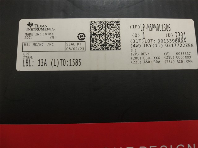
Part Number: LP-MSPM0L1306
Other Parts Discussed in Thread: MSPM0L1304, MSPM0L1306, , MSPM0G3507

Hi,

I'm working on an application for the MSPM0L1306/MSPM0L1304 that uses the internal temperature sensor. I have modified the adc12_single_conversion example to use the internal temperature sensor and 1.4V internal reference. With the development board in my desk, I'm getting values around 1900 and 1910, and the TEMP_SENSE_0 value for my chip is 407.

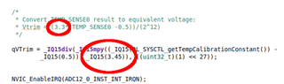
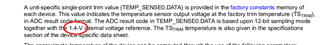
Plugging these values into the formulas from section 2.2.5 of the manual (SLAU847C, as revised on May 2023) I get the following:

VSAMPLE = (1.4 V / 4096) * (1900 - 0.5)  = 649.2 mV

VTRIM = (1.4 V / 4096) * (407 - 0.5) = 138.9 mV

TSAMPLE = (649.2 mV - 138.9 mV) / (-1.75 mV / °C) + 30°C = -262 °C

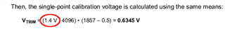
This value is not realistic. However, when using the VTRIM from the example in the manual, I get much more plausible results:

TSAMPLE = (649.2 mV - 634.5 mV) / (-1.75 mV / °C) + 30°C = 22 °C

However, this ignores any per-chip factory calibration, and I'm reluctant to use such a fix in production. I am getting similar results for the other LP-MSPM0L1306.

Am I missing something, or is the TEMP_SENSE_0 value in this chip programmed incorrectly?

Here is the complete FACTORYREGION:

0x41C40000    00000000    1BB8202F    80C2DDD3    02180217    03020301    00001293    00040040    00000000
0x41C40020    00000000    00000000    00000000    00000000    00000000    00000000    00000000    00000197
0x41C40040    00000000    00000000    00000000    00000000    00000000    00000000    00000000    00000000
0x41C40060    00000000    00000000    00000000    00000000    00000000    00000000    00000000    CB6D8077

Software used: Ubuntu 22.04, Code Composer Studio 12.5.0.00007, ARM GCC 10.3-2021.10, MSPM0 SDK 1.20.00.05

Please find attached an archive of the modified example code, as well as the compiled binary.

Thank you,

Balint

adc12_single_conversion.zip

  • Did you try the sample program from resource explorer?

    adc12_internal_temp_sensor_mathacl.c

  • Hi Keith,

    no, I didn't consider that example as that didn't exist for the device I am using. After porting that example over from the MSPM0G1307, I get -146°C. No dice.

    Let me check the differences.

    • I get 807 ADC counts. This is because the example uses the 3.3V VDDA value as reference. The VSAMPLE value ends up being 649.8 mV, so this is consistent.
    • The example uses the same calibration value *0x41C4003C == 407
    • The example calculates VTRIM to be 342 mV. This is because it uses 3.45 V as the reference, contrary to either device's reference manual. (SLAU847C and SLAU846A, both of which specify 1.4 V)

    • Oddly enough, the example uses a temperature coefficient of 1.75 mV / °C instead of 1.8 mV / °C as documented for the MSPM0G1307. This matches the documentation for the MSPM0L1306, but in any case, this shouldn't cause order-of-magnitude errors.

    Once I "fix" the reference voltage, I get back to VTRIM = 139 mV, and I get a final result of -262°C, as before.

    Please find attached the modified example code once again.

    adc12_internal_temp_sensor_mathacl_LP_MSPM0G3507_nortos_gcc.zip

  • Hi Balint Kovacs

    Could you please kindly comment which board you are using?

    and which device you are selected MSPM0G1307 or MSPM0L1306?

    Thanks!

  • Hi Xiaodong,

    I am using the LP-MSPM0L1306. On the first example, I have imported the corresponding example from the SDK, only modifying the source.

    On the second, I got one from the Resource Explorer that was intended for the MSPM0G3507, and ported it over to the MSPM0L1306. (Sorry, I didn't change the name of the project there.) The main steps were:

    1. Change the device and board type in Syscfg
    2. Remove the MATHACL peripheral
    3. Change the IQMath library version to RTS (since the MATHACL isn't available)
    4. Compare the constants in the source to the manuals of either chip

    In any case, the second example didn't really change my results.

  • OK, I had a chance to dive into this. I ran the program on my MSMP0G3507 launchpad.

    Constants:

    #define TEMP_TS_TRIM_C                                            ((uint32_t)30)
    /*
     * Constant below is (1/TSc). Where TSc is Temperature Sensor coefficient
     * available in the device datasheet
     */
    #define TEMP_TS_COEF_mV_C                                             (-571.42f)

    #define ADC_VREF_VOLTAGE                                                  (3.3f)
    #define ADC_BIT_RESOLUTION                                   ((uint32_t)(1)<<12)
    DL_SYSCTL_getTempCalibrationConstant() returns 763.0
    dVTrim = 3.45 * ((double)DL_SYSCTL_getTempCalibrationConstant() - 0.5) / 4096.0;
    dVTrim = 3.45 * (763 - 0.5)/ 4096 = .6422
    [I have no idea why the 3.3 changed to 3.45]
    The ADC return 805 counts so
    dVSample = ADC_VREF_VOLTAGE * (adcResult - 0.5) / ADC_BIT_RESOLUTION;
    dVSample = .64816...
    dTsample = (TEMP_TS_COEF_mV_C * (dVSample - dVTrim)) + TEMP_TS_TRIM_C;
    dTSample = -571.42 * (.64816 - .6422) + 30 = 26.61
    So mine makes sense.
  • Thank you, that's a good new data point. I think this implies that the problem is in the VTRIM formula. It seems that the reference manual is wrong on that 1.4V reference voltage for the MSMP0G3507. It also seems like that either:

    • My LP-MSPM0L1306's have the wrong calibration constant
    • The correct VTRIM formula is a third formula, different from what's in the documentation or in the example for the MSMP0G3507.

    I'm still unsure how to proceed from here, it would be very helpful to confirm these suspicions.

  • Hi, 

    Where and when did you get these LP-MSPM0L1306?

    -

    Early samples' [0x41C4003C, TEMP_SENSE0] is incorrect.

    -

    Reading result from TEMP_SENSE0 of my latest LP-G3507 is 766.

    Comparing with 's reading result 763.0, you can set a fixed number if you use this VTRIM in the development.

    By the way, the example code will work normally on the latest LaunchPad.

    -

    Thank you, .

    -

    Regards,

    Helic

  • Hi Helic,

    I got my LP-MSPM0L1306's from mouser.co.uk, with the order placed on 13th of November, 2023. Please find attached a picture of the label on the box of one of them.

    Thank you,

    Balint

  • Hi, 

    According to the factory region you have read, (0x41C40000)

    It should be early sample that didn't have right temp trim.

    By the way, this 3.45 should be 3.3V, it will be changed in next few updates.

    Thank you for your feedback.

    Regards,

    Helic

  • Hi Helic,

    Thank you, that's very good to know, as well as confirming that 3.3V should be used in the VTRIM formula. One last thing, is there any way we can avoid buying the affected components in the future?

    Thank you,

    Balint

  • Hi, 

    These chips are OK functional evaluation.

    You can pay attention to Seal DT on LP and confirm with your vendor before your purchase.

    Regards,

    Helic

  • Hi Helic,

    We aren't planning on buying any more LaunchPad boards, but for example if we bought 1000 for the first production run, do we need to be concerned? We are planning to use MSPM0L1304TRGE specifically.

    Thank you,

    Balint

  • Hi, 

    I do not know what batch of M0L1304 in stock.

    Please get in touch with your local TI sales.

    If you are worrying about the chips you bought having the same issue, you can contact sales to discuss solutions before your purchase.

    Such as, you can test a few samples with the same batch of 1000 pics firstly. If still have wrong Vtrim, you can ask for a refund and return.

    Regards,

    Helic