This thread has been locked.

If you have a related question, please click the "Ask a related question" button in the top right corner. The newly created question will be automatically linked to this question.

AM2634: Hardware triggered ADC conversion takes 6.7us to generate an interrupt.

Part Number: AM2634

Hello Team,

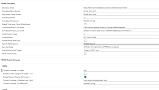
I have configured 3 ADC units with same hardware trigger (EPWM SOC hardware trigger). And Each ADC Unit contains 6 channels each with sample window 64.

We are using clock configurations from gel file only. and ADC prescalar value selected is ADC_CLK_DIV_8_5 for all 3 units.

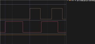
The taken for the conversion between the pwm interrupt to start of ADC interrupt is about 6.77us. 

And one mor point, this 6.77us is irrespective of the number of channels configured. if each unit contain 1 channel, that case also time is 6.77us only.

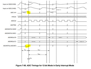
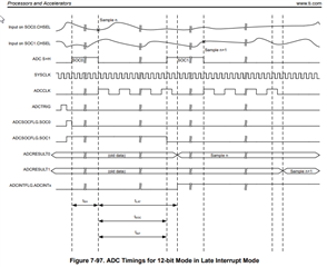
 As per technical reference manual,

The time from pwm Interrupt (Hardware trigger) to start of ADC interrupt = (S+ H time) + Conversion time.

S+H time = 64*5ns = 320ns

conversion time = 11.5 times ADCCLK = 11.5 /(200Mhz/8.5) = 488.75ns

Since it is a synchronized conversion, interrupt will be generated at the end of acquisition window of SOC5. i guess after 6*320ns, right?

1. But why it is taking 6.7us to generate an ADC interrupt?

Could you please provide feedback for this?

2. Can we optimize the timing between PWM trigger and Start of ADC conversion? How it is possible?

Thanks and Regards

Aswathy J G


  • Hello Aswathy,

    What frequency are you running the PWM at? 150kHz?

    I'll pull together full details tomorrow on what could be happening here, but having that figure will help with outlining what is occurring.

    Best Regards,

    Ralph Jacobi

  • Hello Ralph,

    PWM frequency is 5khz.

    I have one more observation, when I tried with 100khz PWM frequency, Conversion is not happening for 3rd ADC unit.

    Hope you will share the feedback today itself.

    Thanks and Regards

    Aswathy J G

  • Hello Aswathy,

    After reviewing every detail you provided today, I don't complete answer yet but I'll share what I can to get you some information to consider.

    What stood out yesterday was that the ADC calculations you had were outdated - we've updated the TRM to reflect them better and included a table for Conversion times as well. I thought this would explain everything, however using your setup with the right set of equations / values, I wasn't able to quite get to your mark. Rather I'm calculating 4.53 uS.

    The sample & hold time you have are very close. It's the (Sample window + 1) * SysClock cycles which comes out to 325ns.

    But the acquisition time should be based on Table 7-101. ADC Timings in 12-bit Mode with SAMPCAPRESETSEL = 1 (This table should be titled INTPULSEPOS = 1...)

    On this table when using 8.5 as the prescalar, your Conversion time would be 86 SysClock cycles. That would equate to 430ns.

    The interrupt generation being at the end of acquisition window of SOC5 is correct but that window would be at 6 * (325 + 430) ns. Which comes out to 4.53 uS. So there's still a factor that is not quite accurate here. But its definitely longer than what you put forth.

    I have one more observation, when I tried with 100khz PWM frequency, Conversion is not happening for 3rd ADC unit.

    So this is an interesting point because it would give me the impression that the synchronization may not be occurring as intended. If you had 3 ADCs with 6 channels each running in succession instead of have the 3 ADCs synchronized in parallel, then you wouldn't be able to complete the conversions for the third PWM unit at 100kHz PWM.

    Few more questions to try and further unravel this:

    1. How are you determining the time from PWM interrupt to EOC interrupt?
    2. When you used 100KHz, was it with all 18 channels on across the 3 ADC instances? If so, can you try and the same but with 4 channels per ADC instance? Do you get the third unit conversions then? If so that would indicate an issue with the synchronization.
    3. Can you share your complete SysCfg file for the project? Also if you are testing this on a TI EVM, if I know which I can try and run similar.

    Best Regards,

    Ralph Jacobi

  • Hello Ralph,

    I am using CPU Cycle counter for measuring time.

    1. How are you determining the time from PWM interrupt to EOC interrupt?

              I have configured a call back from PWM interrupt. Start measuring from PWM callback to Start of the ADC Interrupt routine.

    2. Sorry, this is my mistake, Conversion is happening even with 100Khz, but the problems are in saving the value from the register to a buffer in an ADC ISR routine. If I am using 100khz, only two ADC unit values are updated in the buffer. This has nothing to do with ISR time. 

    I have few more questions,

    1, Theoretically, Sample and hold time and conversion time for 6 channels is 4.53us. but in my case, it is around 6.7us. Do you have any idea why i am taking 2us more?

    2. As per AM263x_TRM_NOV_2022.pdf ,

    Interrupt is generating after the first sample and hold time. see the highlighted portion in attached image.

    But in our discussion, you confirmed that interrupt is generating after sample and hold time of SOC5. Could you please clarify this image?

    Thanks and Regards

    Aswathy J G

  • Hi Aswathy,

    But in our discussion, you confirmed that interrupt is generating after sample and hold time of SOC5. Could you please clarify this image?

    I can answer this one immediately. The figure you've shared is for Early Interrupt mode.

    However you've said the following:

    Since it is a synchronized conversion, interrupt will be generated at the end of acquisition window of SOC5

    Based on this, I am expecting that the configuration used would be based on late interrupt mode which is the normal usage for most applications:

    This is the setting used in our examples except the dedicated early interrupt example:

    Best Regards,

    Ralph Jacobi

  • Hi Ralph,

    In my configuration, interrupt is configured to generate at the end of acquisition window. This is the reason why I expect the interrupt to be at the end of acquisition window of 5th SOC , since I have 6 channels in my ADC unit.


    1. Could you please confirm, when will be the interrupt generation (3 adc units with same hardware trigger and each contains 6 channels with same sample window as mentioned in the earlier post)?

    2. During testing, I have used 20khz PWM for generating interrupt. and interrupt is generating in the low to high transition. at the begining ADC iSR is generating after 5 to 7 us.  but after some time, it takes 14us to 17us to generate ADC ISR.after that i am not getting any ADC ISR.

    Why this conversion time shows differences from 7us to 17us.? 

    In below image, first image shows ADC ISR routine and second shows pwm. The difference shows the time required to generate ADC ISR

    Please comment.

  • Hi Aswathy,

    I'm going to try and get another team member pulled in to help with this as I haven't been able to dig into the details enough here. 

    Best Regards,

    Ralph Jacobi

  • Hi Aswathy,

    I've been reviewing the information in the previous posts.

    I have a few questions/comments.

    1. Can you provide the EPWM Trigger configuration and ADC SOC configuration code you are using?
    2. Have you reviewed the ADC Multiple SOC EPWM example in the latest SDK? (See EXAMPLES_DRIVERS_ADC_MULTIPLE_SOC_EPWM)
    3. Have you verified that there are no overflows by checking the ADCINTOVF and ADCSOCOVF1 registers?
    4. What are you using for VREF?
    5. What kind of circuit is being used to drive the ADC input? Have you modeled your signal conditioning circuit to determine the optimum acquisition sample size based on the drive strength of the input circuit? Please refer to the information provided in this app note (SPRACT6).
    6. One thing to try is to use 2 available GPIO pins and for both the EPWM ISR and ADC ISR, toggle the signal ON at the beginning of the ISR and OFF before leaving the ISR. This will give you some insight into the time taken for each ISR. Also please verify that there are no interrupt overflows by checking the ADCINTOVF and ADCSOCOVF1 registers.

    If you have a consistent EPWM trigger and aren't changing the S+H time, I don't understand why the interrupt ISR generation time would change as you've mentioned above. Please provide feedback and we will continue to look into this issue.

    Best Regards,

    Zackary Fleenor

  • Hello Fleenor,

    Can you provide the EPWM Trigger configuration and ADC SOC configuration code you are using

    For ADC - Configuration is generated from EB Mcal configuration and we are using Mcal Autosar code for testing. Configured with EPWM0 hardware trigger in ADC0, ADC1 and ADC2.

    PWM- Configuration is as follows

    EPWM_setTimeBasePeriod(CONFIG_EPWM0_BASE_ADDR, 1000);

    EPWM_setTimeBaseCounterMode(CONFIG_EPWM0_BASE_ADDR, EPWM_COUNTER_MODE_UP);

    EPWM_clearEventTriggerInterruptFlag(CONFIG_EPWM0_BASE_ADDR);

    /* Enable event counter init for SOCA */
    EPWM_enableADCTriggerEventCountInit(CONFIG_EPWM0_BASE_ADDR, EPWM_SOC_A);
    /* Set the event counter init value to 0 */
    EPWM_setADCTriggerEventCountInitValue(CONFIG_EPWM0_BASE_ADDR, EPWM_SOC_A, 0);
    /* Force the event counter init value to event counter */
    EPWM_forceADCTriggerEventCountInit(CONFIG_EPWM0_BASE_ADDR, EPWM_SOC_A);
    EPWM_clearADCTriggerFlag(CONFIG_EPWM0_BASE_ADDR, EPWM_SOC_A);

    EPWM_enableADCTrigger(CONFIG_EPWM0_BASE_ADDR, EPWM_SOC_A);
    EPWM_setADCTriggerSource(CONFIG_EPWM0_BASE_ADDR, EPWM_SOC_A, EPWM_SOC_TBCTR_ZERO, EPWM_SOC_TBCTR_ZERO);
    EPWM_setADCTriggerEventPrescale(CONFIG_EPWM0_BASE_ADDR, EPWM_SOC_A, 1);

    2. Have you reviewed the ADC Multiple SOC EPWM example in the latest SDK? (See EXAMPLES_DRIVERS_ADC_MULTIPLE_SOC_EPWM)

    but this configuration is working with EPWM frequency 10khz without any problem. And with 20khz if ADC interrupt priority is high.

    using 20khz and without any priority configuration for adc interrupt, it will stop after some time and then ADCINTOVF and ADCSOCOVF15 registers will be set.

    3. Have you verified that there are no overflows by checking the ADCINTOVF and ADCSOCOVF1 registers? 

     ADCINTOVF is set all time.

    Could you please comment based on above details. by that time i will answer your rest of the queries.

    Thanks

  • Hello,

    Can you share the ADC ISR code you are using as well?

    Best Regards,

    Zackary Fleenor

  • Hello, 

    Wanted to check in on the progress here. Are you still experiencing the issue?

    Best Regards,

    Zackary Fleenor