Part Number: EK-TM4C1294XL
Hello,
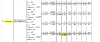
I am currently using the example project for the TI TIVA evaluation board and one of the things I am experimenting with is sleep mode current. According to the datasheet:
- At room temperature
- With Vdd and VDDA set to 3.3V
- With all peripherals off
- and with LDO voltage set to 0.9V
- and with the device running on the 30kHz LFIOSC
I should be able to achieve a device current of 0.454mA.
To measure the device current, I have removed the jumper from JP2 on the evaluation board and have placed a meter in series at this jumper. This allows me to measure current from the +3V3 net to the VDD and VDDA pins on the microprocessor. So I should only be measuring the sleep current of the microprocessor itself and not the rest of the board.
The sleep mode example software uses a UART, 4 LEDs, a push button, a timer (when the device is running), and a PWM module (when the device is in deep sleep). I have commented out all the code for the LEDs, the timer, and the PWM module. I have changed the deep sleep mode LDO voltage setting to 0.9V (and I measure 0.88V to confirm). I have left the push button enabled for convenience, so that I can still easily control when the device is in deep sleep mode.
I would expect to have a current draw in deep sleep mode close to the datasheet value, but instead I measure 3.95mA (about 8x what is expected).
I will attach my modified source file from the sleep mode example.
Can you tell me what I need to do to achieve the datasheet 0.454mA current draw?