This thread has been locked.

If you have a related question, please click the "Ask a related question" button in the top right corner. The newly created question will be automatically linked to this question.

TM4C1292NCPDT: Unlocking the MAC address

Part Number: TM4C1292NCPDT
Other Parts Discussed in Thread: UNIFLASH

Hi,

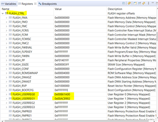
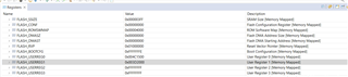
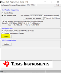
I need help in unlocking the MAC address to restore it to factory settings.

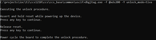
I followed the sequence in the document spma075.pdf by using the command  since I'm using the XDS200 programmer and following the subsequent instructions of holding and releasing the reset button but I'm unable to unlock the MAC address.

Could you please help in finding what I could be missing?

Best Regards,

Kiran

  • Hi,

      Do you have the log after you apply “dbgjtag.exe –f @xds200 –Y unlock,mode=tiva"? What does it say?

      What was the program that was last stored in the flash? Is that program still running?

      Can you even reload the same program or even a new program? Try to reload a simple blinky or hello program. Will it reload successfully? If you can reload any program then it proves that the JTAG interface and DAP are still working. 


  • Hi Charles,

      Do you have the log after you apply “dbgjtag.exe –f @xds200 –Y unlock,mode=tiva"? What does it say?

    Where to find the log file of this procedure? Please suggest steps to generate log(if not generated)

    Can you even reload the same program or even a new program? Try to reload a simple blinky or hello program. Will it reload successfully? If you can reload any program then it proves that the JTAG interface and DAP are still working. 

    Yes,the program can be loaded and works fine.

    What was the program that was last stored in the flash? Is that program still running?

    Yes,the program is running. 

    Best Regards,

    Kiran

  • Hi Kiranjit,

      What I mean by log is the output you see on the Windows screen after you execute dbgjtag.exe –f @xds200 –Y unlock,mode=tiva". Just take a screenshot of your Windows. 


  • Hi Charles,

    Below is the screenshot of the screen:


    Please share your comments on it.

    Best Regards,

    Kiran

  • It looks normal to me. How do you know the MAC is not erase?

    Why don't you view the USERREG0 and USERREG1 in the flash controller? These two registers store your current MAC address. If you erase them, they should show as all F's. 

  • Hello Charles,

    Do I need to check these in the debug mode? I tried to read the MAC address in Uniflash after performing the above unlock procedure and it was same as the one I programmed. It was not all F's.

    Could you guide if I'm missing something?

    Best regards,

    Kiran 

  • Hi,

      Yes, to check these registers in CCS, you need to first connect to the device and go to the register browser to view them. 


  • Hi Charles,

    The register window after performing the unlock sequence is as below:

    Which shows the MAC address is not all F's even after the unlock procedure.

    Is there any encryption applied on the chip?

    Can you suggest anything else I can try to unlock it?

    Best Regards,

    Kiran

  • Hi Kiranjit,

      Can you try some experiments?

      - Can you use the XDS200 debug probe on the LaunchPad and try the dbgjtag.exe on the LaunchPad?

      - Follow section 4.8 to use a LaunchPad to debug out your custom board. The LaunchPad has an onboard ICDI debug probe. With this setup, you can use the Unlock utility that is provided by LM Flash Programmer to unlock and erase the MAC address on  your custom board. LM Flash Programmer only works with ICDI, not XDS200. 

    With the above experiments, we will get a hint if the problem is with dbgjtag.exe or XDS200 or maybe something related to your custom board. 

  • Hi Charles,

    - Follow section 4.8 to use a LaunchPad to debug out your custom board. The LaunchPad has an onboard ICDI debug probe. With this setup, you can use the Unlock utility that is provided by LM Flash Programmer to unlock and erase the MAC address on your custom board. LM Flash Programmer only works with ICDI, not XDS200. 

    I can use only XDS200 for my custom board not ICDI, so LM Flash Programmer doesn't work on my custom board.

    Best Regards,

    Kiran

  • Hi Kiran,

     Here is the link to the app note that I was referring to use the ICDI on a EK-TM4C129XL board to debug out another TM4C chip. https://www.ti.com/lit/pdf/spma075. You will need to create a JTAG connector. If this is not possible, have you tried to use your XDS200 to erase a EK-TM4C129XL board? What is the result?

      I just tried it myself with an XDS200 probe on my LaunchPad. Here is the result. See below. 

    I use CCS to view the USER_REG0 and USER_REG1 and they become all F's on my LaunchPad. The board originally have a valid MAC address. 

    If I use ICDI and LM flash programmer to view the MAC address, they also show all F's. 


    I will suggest you update the XDS200 driver to see if it makes a difference. Refer to this link and search for 'To reinstall the Windows device drivers:'. Reinstall the Windows driver for XDS200 and see if you can erase the MAC address. 

    https://software-dl.ti.com/ccs/esd/documents/xdsdebugprobes/emu_xds200.html

  • Hi Charles,

    If this is not possible, have you tried to use your XDS200 to erase a EK-TM4C129XL board? What is the result?
      I just tried it myself with an XDS200 probe on my LaunchPad. Here is the result. See below.

    I didn't understand how to use XD200 probe on the Launchpad. Can you please share the picture of your setup?

    Best Regards,

    Kiran

  • You can connect to the U6 JTAG connector for external debug. 

  • Hi Kiranjit,

       I have not heard back from you. I will close the post for now. If you have any update you can write to this post and the post will change the status OPEN. 

  • Hello Charles,

    Sorry for reverting back late. But the connector on the TI evaluation board is 10 pins but the connector on the Debug probe is of 20 pins.

    Please guide how to connect it.

    Best Regards,

    Kiran

  • Sorry for reverting back late. But the connector on the TI evaluation board is 10 pins but the connector on the Debug probe is of 20 pins.

    You need an 20 pin to 10 pin adapter. When you purchase XDS200 debug probe, it should come with the adapter.