This thread has been locked.

If you have a related question, please click the "Ask a related question" button in the top right corner. The newly created question will be automatically linked to this question.

LAUNCHXL-CC1310: CC1310

Part Number: LAUNCHXL-CC1310
Other Parts Discussed in Thread: CC1310

Hello everyone.
I am working with a SPI slave device.
Which requires the host to send an 8 byte command and the slave responds with an IRQ for the host to issue two bytes of mode change (host read or host write).
When sending the two mode change bytes, 8 bytes of information are expected to be received.
Exploring the Simplelink CC13XX SPI.h examples, I only notice that the TX and RX buffer size are the same size.
Does anyone know how to send 2 bytes and receive 8 bytes?


I have tried this idea, but it doesn't work for me.

transaction.count = 2;
transaction.txBuf = &data;
transaction.count = 8;
transaction.rxBuf = &RXdata;
spiTransferOk = SPI_transfer(RED2_Spi, &transaction);

Regards.

  • No sure I understand the problem, and an SPI plot of what you are trying to achieve would be helpful.

    However, if you want to read 8 bytes from the slave, the Master needs to generate the clock and send something on the MOSI line. If there are no requirements ton the slave side as to what that is, you can send whatever dummy bytes you want.

    Assuming that you need something like this:

    The transaction needs to be 10 bytes (the two mode change bytes and the 8 dummy bytes), and the Slave will transmit 8 data bytes after the mode change bytes are received. The two first bytes received will be don't care, unless the slave is sending something useful here.

    As I said, it is not possible to answer more specific when I do not know exactly what you are trying to do.

    Siri

  • Hi Siri.

    Attached is an SPI plot of what I hope to achieve.

    Carefully observe the IRQ and CS signals.

    thanks for your help

  • Here is what I did for my L6470 stepper driver. This function gets 3 bytes.

    uint32_t GetParam3(uint8_t param)
    {
    
        uint8_t rxdata = 0;
        uint32_t data = 0;
    
        // Send command
        MAP_GPIO_setOutputLowOnPin(GPIO_PORT_P2, GPIO_PIN4);
    
        SPI_transmitData(EUSCI_B0_BASE, GET_PARAM | param);
    
        while (!(SPI_getInterruptStatus(EUSCI_B0_BASE, EUSCI_SPI_TRANSMIT_INTERRUPT)));
    
        while (!(SPI_getInterruptStatus(EUSCI_B0_BASE, EUSCI_SPI_RECEIVE_INTERRUPT)));
    
        // should be 0
        rxdata = SPI_receiveData(EUSCI_B0_BASE);
    
    
        MAP_GPIO_setOutputHighOnPin(GPIO_PORT_P2, GPIO_PIN4);
        MAP_GPIO_setOutputLowOnPin(GPIO_PORT_P2, GPIO_PIN4);
    
        // Get MSB
        SPI_transmitData(EUSCI_B0_BASE, NOP);
        while (!(SPI_getInterruptStatus(EUSCI_B0_BASE, EUSCI_SPI_TRANSMIT_INTERRUPT)));
    
        while (!(SPI_getInterruptStatus(EUSCI_B0_BASE, EUSCI_SPI_RECEIVE_INTERRUPT)));
    
        rxdata = SPI_receiveData(EUSCI_B0_BASE);
        data = (rxdata << 16);
    
        MAP_GPIO_setOutputHighOnPin(GPIO_PORT_P2, GPIO_PIN4);
        MAP_GPIO_setOutputLowOnPin(GPIO_PORT_P2, GPIO_PIN4);
    
        // Get middle bit
        SPI_transmitData(EUSCI_B0_BASE, NOP);
        while (!(SPI_getInterruptStatus(EUSCI_B0_BASE, EUSCI_SPI_TRANSMIT_INTERRUPT)));
    
        while (!(SPI_getInterruptStatus(EUSCI_B0_BASE, EUSCI_SPI_RECEIVE_INTERRUPT)));
    
        rxdata = SPI_receiveData(EUSCI_B0_BASE);
        data = data | (rxdata << 8);
    
        MAP_GPIO_setOutputHighOnPin(GPIO_PORT_P2, GPIO_PIN4);
        MAP_GPIO_setOutputLowOnPin(GPIO_PORT_P2, GPIO_PIN4);
    
        // Get Second Byte
        SPI_transmitData(EUSCI_B0_BASE, NOP);
        while (!(SPI_getInterruptStatus(EUSCI_B0_BASE, EUSCI_SPI_TRANSMIT_INTERRUPT)));
    
        while (!(SPI_getInterruptStatus(EUSCI_B0_BASE, EUSCI_SPI_RECEIVE_INTERRUPT)));
    
        rxdata = SPI_receiveData(EUSCI_B0_BASE) ;
        data |= rxdata;
    
        MAP_GPIO_setOutputHighOnPin(GPIO_PORT_P2, GPIO_PIN4);
    
        return data;
    }

    Note that the first byte is the parameter I want, and then I send NOPS to get the other bytes.

  • I took the following SPI Master example from the SDK and simplified it a alot.

    unsigned char masterRxBuffer[8];
    unsigned char masterTxBuffer[8] = {0x00, 0x00, 0x00, 0x00, 0x00, 0x00, 0x00, 0x00};
    
    void *masterThread(void *arg0)
    {
        SPI_Handle      masterSpi;
        SPI_Params      spiParams;
        SPI_Transaction transaction;
    
        /* Open SPI as master (default) */
        SPI_Params_init(&spiParams);
        spiParams.frameFormat = SPI_POL0_PHA1;
        spiParams.bitRate = 4000000;
        masterSpi = SPI_open(Board_SPI_MASTER, &spiParams);
        if (masterSpi == NULL) {
            while (1);
        }
    
        transaction.txBuf = (void *) masterTxBuffer;
        transaction.rxBuf = (void *) masterRxBuffer;
    
        while(1)
        {
            transaction.count = 2;
            
            // Whatever the MODE CHANGE instruction is
            masterTxBuffer[0] = 0x55;
            masterTxBuffer[1] = 0xCC;
    
            SPI_transfer(masterSpi, &transaction);
    
            transaction.count = 8;
            // 8 dummy bytes when receiving 8 bytes from the slave
            masterTxBuffer[0] = 0x00;
            masterTxBuffer[1] = 0x00;
    
            SPI_transfer(masterSpi, &transaction);
    
            usleep(10000);
        }
    }

    On the SPI it looks like this:

    My master is not connected to any slave, so nothing is returned on the MISO, and there are no Interrupt line

    SIri

  • Hi Keith Barkley

    Thank you very much for your contribution.

    Best regards.

  • Hi Siri.

    Thank you very much for your help :)
    The concept of sending dummy bytes solved part of the problem for me.
    I will continue testing based on the information and example provided, as soon as I have results I will report them.

    One more doubt, how do you control the CS pin state change time? In my case I have it routed on the DIO12 pin, which does not correspond to the default SPI implementation.

    Best regards.

  • The timing of when the CS signal is pulled low and high is determined by the driver implementation and is not a parameter that is configurable from the application. Why do you have to change?

    Please see the following post on how to assign the SPI pins to other pins than what is used on the CC1310 Launchpad.

    (+) LAUNCHXL-CC1310: Configuration process for a GPIO Pin - Arm-based microcontrollers forum - Arm-based microcontrollers - TI E2E support forums

    Siri

  • In my case, I was using 3 wire SPI so that I controlled CS. It was a GPIO (2.4) that is totally under program control as shown in my code.

  • Hi Siri.

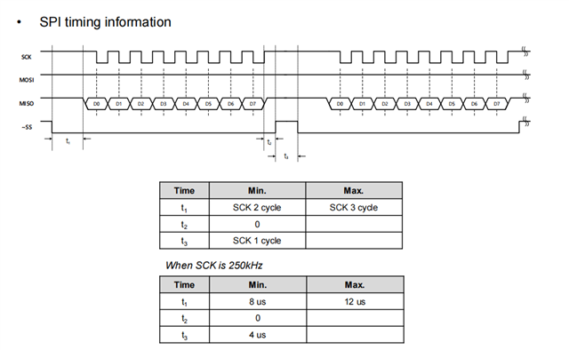
    Can you check the images please.
    The low to high CS times of the SPI driver are mismatched for the implementation required by my slave module.
    I am sending frames from the master with a rate of 250 KHz and I get no response from the slave.

    I wonder if that microsecond difference could really affect my communication.
    Any ideas to improve those times?
    Best regards.

  • I forgot to mention that for these tests I am using the default pin configuration of the SPI driver.

  • If the timing of the CSn signal is a problem or not for your slave module, you need to ask the the slave module provider, I cannot answer that.

    If you want to control the CSn manually, you can set .csnPin = PIN_UNASSIGNED in spiCC26XXDMAHWAttrs, and then set up the CSn signal to be controlled by the application (look at the post i referred to Jan. 26th on how to do this).

    You application could look something like this:

    unsigned char masterRxBuffer[1];
    unsigned char masterTxBuffer[1];
    
    void *masterThread(void *arg0)
    {
        SPI_Handle      masterSpi;
        SPI_Params      spiParams;
        SPI_Transaction transaction;
    
        /* Open SPI as master (default) */
        SPI_Params_init(&spiParams);
        spiParams.frameFormat = SPI_POL0_PHA1;
        spiParams.bitRate = 250000;
        masterSpi = SPI_open(Board_SPI_MASTER, &spiParams);
        if (masterSpi == NULL) 
        {
            while (1);
        }
    
        transaction.txBuf = (void *) masterTxBuffer;
        transaction.rxBuf = (void *) masterRxBuffer;
        transaction.count = 1;
    
        GPIO_setConfig(Board_SPI0_CSN, GPIO_CFG_OUTPUT | GPIO_CFG_OUT_HIGH);
    
        while(1)
        {
            GPIO_write(Board_SPI0_CSN, 0);
            masterTxBuffer[0] = 0x55;
            SPI_transfer(masterSpi, &transaction);
            GPIO_write(Board_SPI0_CSN, 1);
    
            CPUdelay(DELAY_TIME);
    
            GPIO_write(Board_SPI0_CSN, 0);
            masterTxBuffer[0] = 0xCC;
            SPI_transfer(masterSpi, &transaction);
            GPIO_write(Board_SPI0_CSN, 1);
    
            CPUdelay(DELAY_TIME);
    
            uint8_t i = 0;
            for(i = 0; i < 8; i++)
            {
                GPIO_write(Board_SPI0_CSN, 0);
                masterTxBuffer[0] = 0x00;
                SPI_transfer(masterSpi, &transaction);
                GPIO_write(Board_SPI0_CSN, 1);
                CPUdelay(DELAY_TIME);
            }
            usleep(10000);
        }
    }
    

    Siri

  • Hello Siri.
    My problem has been solved by applying concepts from the information provided.
    Thank you very much.