This thread has been locked.

If you have a related question, please click the "Ask a related question" button in the top right corner. The newly created question will be automatically linked to this question.

TM4C1294KCPDT: Current all peripherals off during POR with LDO inrush

Guru 55913 points
Part Number: TM4C1294KCPDT
Other Parts Discussed in Thread: TPS735, TPS717

Hello forum gurus,

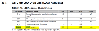
Why the datasheet current consumption table and LDO table 27-63 does not show a formula (Iinrush) though table 27-8 shows LDO ranges 50mA - 150mA? Do we assume LDO Iirush depends on how many peripherals are enabled after POR? It's not a launch pad sporting 500mA LDO though seem to recall runtime current being roughly 78mA steady state. Was there ever Tina model made for TM4C1294?

Table shows all peripherals off (65.3mA 105°C) so we have to also add LDO inrush to that? Also does not account for 3v3 rail capacitors and any bulk caps in the circuit though large capacitance on 3v3 rail slows down the rate of total inrush via external LDO.

So external 500mA -1A LDO regulator is no big mystery but downsizing to external 150mA LDO raises some questions. For instance, C2000 MCU current consumption might reach >170mA during flash write. I could not find any similar datasheet text TM4C flash write via internal LDO or external 3v3 rail though seem to recall it being mentioned this forum some time ago.

The trade off on external LDO current seems to be relative to PSRR range to that of high frequency buck regulators that may supply LDO input.

  • Hi BP101,

     What exactly are you looking for? Inrush current is showed below. 

    Hope this FAQ is useful for inrush current explanation. https://e2e.ti.com/support/power-management-group/power-management/f/power-management-forum/1127642/faq-inrush-current-from-an-ldo-perspective

  • Why BP101 the avatar lists Genatco our trade name?

    What exactly are you looking for?

    As explained above does that include CPU, NVIC, peripheral current too? So 250mA seems a bit excessive for CMOS LDO has anyone TI actually confirmed that in LAB analysis other than datasheet table? What about Tina model?

    FYI: Table 27-15 does not show actual LDO run time current as the FAQ relates to a known inrush current level and time period graph.

  • I'm not an LDO expert. My understanding is that the Inrush current occurs during the time when the LDO regulator turns on to the time when the output voltage stabilizes. The LDO drives the output transistor between the input and output with the maximum drive capability to raise the output voltage to the programmed level. I don't think it includes the CPU, NVIC and peripheral current during this time yet. Until the VDDC is stabilized, the circuits that depend on the 1.2V are still held by the internal reset. 

    We don't have Tina model for TM4C. 

  • Hi Charles,

    Thank you for your analysis time!

    Recall launch pad JP2 removed drew 120mA unless +VBUS pin was partially shorted did current spike during POR. Anyway, the new TI 48v buck regulator design has soft start ramp (300ms) should reduce inrush external +3v3 LDO output has startup ramp period too. Revision 13 PCB had TPS735 500mA LDO, the PSRR is not as robust as TPS717 touting ultralow PSRR 1MHz 45db. Oddly the TPS735 gets pinky warm even with thermal vias bottom side. TPS735 has output overshoot protection, TPS717 does not and should be better for the far placed LDO closer to 20KHz high voltage PWM.

    Peripheral line up: 5x GPTM, EMAC0, PHY, USB0 disabled, HIB disabled, PWM0 x6 GPIO @8mA SC, ADC0, GPIO ports - 4 LED 6mA drive, CCP0/1, analog COMP x3, CAN0, JTAG