This thread has been locked.

If you have a related question, please click the "Ask a related question" button in the top right corner. The newly created question will be automatically linked to this question.

MSPM0C1104: Issue with I2C memory read with BQ76952

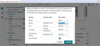
Part Number: MSPM0C1104
Other Parts Discussed in Thread: BQ76952, MSPM0L1306, , SYSCONFIG

Dear mam,

    I am using M0C1104 (TSSOP20 package) for i2c communication. In CSS,I am facing issues in reading memory location using I2c with EEPROM(M24C08) and BQ76952.

I am able to read correct data on some memory locations but on other locations I am getting garbage data.

Tested I2C SCL clock is 100khz /400Khz for EEPROM and 400 Khz for BQ76952.

Function used: I2C_ReadReg(COMMAND, RX_Data, 2);

7 bit I2C_TARGET_ADDRESS = 0x50 ( for eeprom 0xA0 >>1)   and 0x08 (for bQ76952 0x10 >> 1)

#include "BQ769x2_protocol.h"


uint8_t RX_Data[4];
volatile uint8_t COMMAND = 0x0E;

int main(void)
{
   SYSCFG_DL_init();
  DL_SYSCTL_disableSleepOnExit();

  while (1)
  {
    I2C_ReadReg(COMMAND, RX_Data, 2);
  }
}

And as per your suggestion to migrate the code of BQ76952 with MSPM0L1306 to MSPS003FX  for our controller we used the suggested process.

but we are unable to get through, we found following problem

"CORTEX_M0P: Loader: One or more sections of your program falls into a memory region that is not writable. 

These regions will not actually be written to the target.  Check your linker configuration and/or memory map."


Please provide us the example code of BQ76952 with MSPM0C1104 and help with what might be the problem for I2C to not work properly.

Thank You

  • Hi 

    Here is the app note: BQ769x2 Control Based on MSPM0 Through I2C (ti.com) Hope it will help you.

    And for EEPROM read, please try to use demo code in SDK.

    B.R.

    Zoey

  • Hi

    Actually this did not resolve my issue.

    We need a particular example for BQ769x2 with MSPM0C1104 with TSSOP package.

    AND while migrating your code example to MSPS003FX (this is a solution of getting MSPM0C1104 with TSSOP package) I am getting below error.

    "CORTEX_M0P: Loader: One or more sections of your program falls into a memory region that is not writable. 

    These regions will not actually be written to the target.  Check your linker configuration and/or memory map."

    Please guide me how to get rid from this error also provide a particular example for BQ769x2 with MSPM0C1104 with TSSOP package.

    B.R.

    Saurabh 

  • Hi,

    So, your main purpose is to migrating the example code from L1306 to C1104 TSSOP package. 

    But I checked the code it only uses the I2C port (PA0 and PA1) on the L1306. C1104 TSSOP package also has PA0 and PA1. There should be no changes switching between those two MCUs. I also seems that you have a working project on the C1104 MCU. However, there is some issue on the I2C communication. Could you described more about this issue so we can help on it?

    I am able to read correct data on some memory locations but on other locations I am getting garbage data.

    Best regards,

    Cash Hao

  • Hi,

    Yes, I checked the L1306 Example of BQ76952 has  PA0 and PA1 pin for I2C.

    and yes our main purpose is to migrating the example code of BQ76952 from L1306 to C1104 TSSOP package. 

    Issue with I2C is:

    I opened i2c_controller_rw_multibyte_fifo_poll Example from Resource Explorer with M0C11004 (VSSOP).

    I edited its main function and add all functions from BQ76952 Example  to read cell voltages.

    Result is I am not getting any values.

    only if I comment  DL_I2C_flushControllerTXFIFO(I2C_INST); function in  I2C_ReadReg() function.

    then I receive values in CellVoltage array but these values are not accurate to cell voltages .

    This is my code .

    /*
     * Copyright (c) 2021, Texas Instruments Incorporated
     * All rights reserved.
     *
     * Redistribution and use in source and binary forms, with or without
     * modification, are permitted provided that the following conditions
     * are met:
     *
     * *  Redistributions of source code must retain the above copyright
     *    notice, this list of conditions and the following disclaimer.
     *
     * *  Redistributions in binary form must reproduce the above copyright
     *    notice, this list of conditions and the following disclaimer in the
     *    documentation and/or other materials provided with the distribution.
     *
     * *  Neither the name of Texas Instruments Incorporated nor the names of
     *    its contributors may be used to endorse or promote products derived
     *    from this software without specific prior written permission.
     *
     * THIS SOFTWARE IS PROVIDED BY THE COPYRIGHT HOLDERS AND CONTRIBUTORS "AS IS"
     * AND ANY EXPRESS OR IMPLIED WARRANTIES, INCLUDING, BUT NOT LIMITED TO,
     * THE IMPLIED WARRANTIES OF MERCHANTABILITY AND FITNESS FOR A PARTICULAR
     * PURPOSE ARE DISCLAIMED. IN NO EVENT SHALL THE COPYRIGHT OWNER OR
     * CONTRIBUTORS BE LIABLE FOR ANY DIRECT, INDIRECT, INCIDENTAL, SPECIAL,
     * EXEMPLARY, OR CONSEQUENTIAL DAMAGES (INCLUDING, BUT NOT LIMITED TO,
     * PROCUREMENT OF SUBSTITUTE GOODS OR SERVICES; LOSS OF USE, DATA, OR PROFITS;
     * OR BUSINESS INTERRUPTION) HOWEVER CAUSED AND ON ANY THEORY OF LIABILITY,
     * WHETHER IN CONTRACT, STRICT LIABILITY, OR TORT (INCLUDING NEGLIGENCE OR
     * OTHERWISE) ARISING IN ANY WAY OUT OF THE USE OF THIS SOFTWARE,
     * EVEN IF ADVISED OF THE POSSIBILITY OF SUCH DAMAGE.
     */
    
    #include "ti_msp_dl_config.h"
    /*
     * Number of bytes to send from Controller to target.
     *  This example uses FIFO with polling, and the maximum FIFO size is 4.
     *  Refer to interrupt examples to handle larger packets
     */
    #define I2C_TX_PACKET_SIZE (2)
    
    /*
     * Number of bytes to received from target.
     *  This example uses FIFO with polling, and the maximum FIFO size is 4.
     *  Refer to interrupt examples to handle larger packets
     */
    #define I2C_RX_PACKET_SIZE (4)
    
    #define Cell1Voltage 0x14
    #define StackVoltage 0x34
    #define PACKPinVoltage 0x36
    #define Cell16Voltage 0x32
    #define R 0         //Read
    
    void I2C_Send();
    void I2C_Receive_Controller();
    void delayUS(uint16_t us);
    void I2C_ReadReg(uint8_t reg_addr, uint8_t *reg_data, uint8_t count);
    void DirectCommands(uint8_t command, uint16_t data, uint8_t type);
    uint16_t BQ769x2_ReadVoltage(uint8_t command);
    void BQ769x2_ReadAllVoltages();
    
    
    /* Data sent to the Target */
    uint8_t gTxPacket[I2C_TX_PACKET_SIZE] = {0x14};
    /* Data received from Target */
    uint8_t gRxPacket[2];
    uint16_t CellVoltage[16];
    /* I2C Target address */
    #define I2C_TARGET_ADDRESS   (0x08)//(0x48)
    
    uint32_t gTxLen, gTxCount;
    uint8_t RX_data[2];
    
    uint16_t Cell_voltage;
    uint16_t Stack_Voltage = 0x00;
    uint16_t Pack_Voltage  = 0x00;
    uint16_t LD_Voltage    = 0x00;
    
    
    void delayUS(uint16_t us)
    {  // Sets the delay in microseconds.
        uint16_t ms;
        char i;
        ms = us / 1000;
        for (i = 0; i < ms; i++) delay_cycles(32000);
    }
    
    //************I2C read register **********************
    void I2C_ReadReg(uint8_t reg_addr, uint8_t *reg_data, uint8_t count)
    {
        DL_I2C_fillControllerTXFIFO(I2C_INST, &reg_addr, count);
    
        /* Wait for I2C to be Idle */
        while (!(DL_I2C_getControllerStatus(I2C_INST) & DL_I2C_CONTROLLER_STATUS_IDLE));
    
        DL_I2C_startControllerTransfer(I2C_INST, I2C_TARGET_ADDRESS, DL_I2C_CONTROLLER_DIRECTION_TX, 1);
    
        while (DL_I2C_getControllerStatus(I2C_INST) & DL_I2C_CONTROLLER_STATUS_BUSY_BUS) ;
        /* Trap if there was an error */
        if (DL_I2C_getControllerStatus(I2C_INST) & DL_I2C_CONTROLLER_STATUS_ERROR)
        {
            /* LED will remain high if there is an error */
            __BKPT(0);
        }
        /* Wait for I2C to be Idle */
        while (!(DL_I2C_getControllerStatus(I2C_INST) & DL_I2C_CONTROLLER_STATUS_IDLE));
        /* Add delay between transfers */
        delay_cycles(1000);
        DL_I2C_flushControllerTXFIFO(I2C_INST);
    
        /* Send a read request to Target */
        DL_I2C_startControllerTransfer(I2C_INST, I2C_TARGET_ADDRESS, DL_I2C_CONTROLLER_DIRECTION_RX, count);
    
        for (uint8_t i = 0; i < count; i++)
        {
            while (DL_I2C_isControllerRXFIFOEmpty(I2C_INST));
            reg_data[i] = DL_I2C_receiveControllerData(I2C_INST);
        }
    }
    
    void DirectCommands(uint8_t command, uint16_t data, uint8_t type)
    // See the TRM or the BQ76952 header file for a full list of Direct Commands
    {  //type: R = read, W = write
        uint8_t TX_data[2] = {0x00, 0x00};
    
        //little endian format
        TX_data[0] = data & 0xff;
        TX_data[1] = (data >> 8) & 0xff;
    
        if (type == R) {                       //Read
            I2C_ReadReg(command, RX_data, 2);  //RX_data is a global variable
            delayUS(2000);
            delayUS(2000);  //success in 100k
        }
    //    if (type == W) {  //write
    //        //Control_status, alarm_status, alarm_enable all 2 bytes long
    //        I2C_WriteReg(command, TX_data, 2);
    //        delayUS(2000);
    //        delayUS(2000);
    //    }
    }
    
    uint16_t BQ769x2_ReadVoltage(uint8_t command)
    // This function can be used to read a specific cell voltage or stack / pack / LD voltage
    {
        //RX_data is global var
        DirectCommands(command, 0x00, R);
        if (command >= Cell1Voltage &&
            command <= Cell16Voltage) {  //Cells 1 through 16 (0x14 to 0x32)
            return (RX_data[1] * 256 + RX_data[0]);  //voltage is reported in mV
        } else {                                     //stack, Pack, LD
            return 10 * (RX_data[1] * 256 +
                            RX_data[0]);  //voltage is reported in 0.01V units
        }
    }
    
    void BQ769x2_ReadAllVoltages()
    // Reads all cell voltages, Stack voltage, PACK pin voltage, and LD pin voltage
    {
        unsigned char x;
        int cellvoltageholder = Cell1Voltage;  //Cell1Voltage is 0x14
        for (x = 0; x < 16; x++) {             //Reads all cell voltages
            CellVoltage[x]    = BQ769x2_ReadVoltage(cellvoltageholder);
            cellvoltageholder = cellvoltageholder + 2;
        }
        Stack_Voltage = BQ769x2_ReadVoltage(StackVoltage);
        Pack_Voltage  = BQ769x2_ReadVoltage(PACKPinVoltage);
    }
    
    int main(void)
    {
      SYSCFG_DL_init();
      DL_SYSCTL_disableSleepOnExit();
      while (1) {
    
          BQ769x2_ReadAllVoltages();
    //      I2C_ReadReg();
    //      Cell_voltage =  gRxPacket[1]* 256 +  gRxPacket[0];
         //I2C_Send();
         //I2C_Receive_Controller();
          delayUS(5000);
          }
    }


    and if I  migrate the example code of BQ76952 from L1306 to  MSPS003FX(TSSOP) and do all the operation like I mention above.

    then while switching to debug mode my resume(F8) option is disabled and I got message in Console:

    CORTEX_M0P: Loader: One or more sections of your program falls into a memory region that is not writable.  These regions will not actually be written to the target.  Check your linker configuration and/or memory map.

    please help me how to overcome from  this message. I searched in internet for this message but couldn't find any easy  and understandable solution.

  • Hi,

    migrated the example code of BQ76952 from L1306 to C1104 TSSOP package. 

    I changed the original input pin from PA14 to PA16, since the C1104 TSSOP package does not have PA14 pin. 

    And copy the ti_msp_dl_config.c and ti_msp_dl_config.h to an empty_non_sysconfig project. The project build without errors. You can try with it.