Part Number: MSPM0G3507
Hi sir
i use MSPM0G3507 EVM board to design my application.
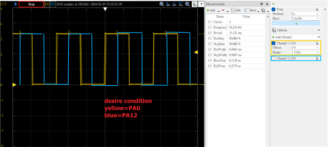
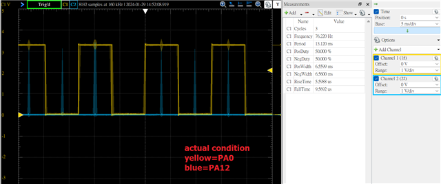
PA0 use for zero event toggle, every 6.5535ms
PA12 use for timer compare match auto toggle, every 6.5535ms
PA0 is ok, no problem but PA12 doesn't work
#include "ti_msp_dl_config.h"
uint16_t counter1;
uint16_t counter2;
void Initial_TIMG0(void);
/********************************************************************/
//
//
//
/********************************************************************/
void Initial_TIMG0(void)
{
DL_TimerG_reset(TIMG0);
DL_TimerG_enablePower(TIMG0);
delay_cycles(POWER_STARTUP_DELAY);
/*
* Timer clock configuration to be sourced by BUSCLK / (40000000 Hz)
* timerClkFreq = (timerClkSrc / (timerClkDivRatio * (timerClkPrescale + 1)))
* 10000000 Hz = 40000000 Hz / (1 * (3 + 1))
*/
static const DL_TimerG_ClockConfig gTIMER_0ClockConfig = {
.clockSel = DL_TIMER_CLOCK_BUSCLK,
.divideRatio = DL_TIMER_CLOCK_DIVIDE_1,
.prescale = 3U,
};
/*
* Timer load value (where the counter starts from) is calculated as (timerPeriod * timerClockFreq) - 1
* TIMER_0_INST_LOAD_VALUE = (6.55 ms * 10000000 Hz) - 1
*/
static const DL_TimerG_TimerConfig gTIMER_0TimerConfig = {
.period = 65535,
.timerMode = DL_TIMER_TIMER_MODE_PERIODIC_UP,
.startTimer = DL_TIMER_STOP,
};
DL_GPIO_initPeripheralOutputFunction(IOMUX_PINCM34, IOMUX_PINCM34_PF_TIMG0_CCP0); // PA12 connect TIMG0 CCR0 peripheral
DL_GPIO_enableOutput(GPIOA, DL_GPIO_PIN_12); // set PA12 use for CCR0 compare match output
DL_TimerG_setClockConfig(TIMG0, (DL_TimerG_ClockConfig *) &gTIMER_0ClockConfig);
DL_TimerG_initTimerMode(TIMG0, (DL_TimerG_TimerConfig *) &gTIMER_0TimerConfig);
DL_Timer_setCaptureCompareValue(TIMG0, 32768, DL_TIMER_CC_0_INDEX); // PA12 delay 3.2767ms to toggle
DL_Timer_setCCPDirection(TIMG0, GPTIMER_CCPD_C0CCP0_OUTPUT); // set CCR0 as compare match output
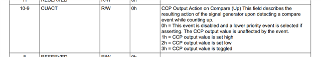
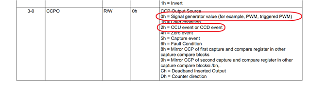
DL_Timer_setCaptureCompareOutCtl(TIMG0, 0, 0, 2, DL_TIMER_CC_0_INDEX); // CCP(PA12) initial in low level, no invert source CCU or CCD event
DL_Timer_setCaptureCompareAction(TIMG0, GPTIMER_CCACT_01_CUACT_CCP_TOGGLE, DL_TIMER_CC_0_INDEX); // PA12 every 6.5535ms toggle
DL_TimerG_enableInterrupt(TIMG0, DL_TIMERG_INTERRUPT_ZERO_EVENT|DL_TIMERG_INTERRUPT_CC0_UP_EVENT);
DL_TimerG_enableClock(TIMG0);
}
/********************************************************************/
//
//
//
/********************************************************************/
int main(void)
{
SYSCFG_DL_init();
Initial_TIMG0();
NVIC_EnableIRQ(TIMG0_INT_IRQn);
//DL_SYSCTL_enableSleepOnExit();
DL_TimerG_startCounter(TIMG0);
while (1)
{
__NOP();
}
}
void TIMG0_IRQHandler(void)
{
switch (DL_TimerG_getPendingInterrupt(TIMG0))
{
case DL_TIMER_IIDX_ZERO:
counter1++;
DL_GPIO_togglePins(GPIO_LEDS_PORT, GPIO_LEDS_USER_LED_1_PIN); // PA0 every 6.5535ms toggle
break;
case DL_TIMER_IIDX_CC0_UP: // PA12 every 6.5535ms auto toggle
counter2++;
break;
default: break;
}
}
please help me to to resolve why PA12 can't auto toggle, thanks
i offer this project detail in my google drive