This thread has been locked.

If you have a related question, please click the "Ask a related question" button in the top right corner. The newly created question will be automatically linked to this question.

MCU-PLUS-SDK-AM243X: LP-AM243: How to set up several direct GPIO interrupts (no bank interrupt)

Part Number: MCU-PLUS-SDK-AM243X
Other Parts Discussed in Thread: SYSCONFIG

Hi,

I am trying to snap the encoderdata (EQEP) and a timestamp (by ECAP module) for 4 external devices. For this purpose, I would run a trigger line from each device to the EQEP and ECAP modules via an OR-Gutter so each device can trigger a value capturing. 

Additionally I would route each signal to its own GPIO with its own ISR. So I could then query the last caputured values from the modules in the ISRs. The distinction between who has just triggered is then made by the fact that each device receives its own ISR.

So I know with sysconfig I can setup bank interrupts and I also managed to use two of them to trigger two different ISRs. But I don't have the free choice of GPIOs and can simply use one pin from each of 4 different banks, so I need direct GPIO interrupts here.

I already searched through the e2e and found the possibility two differ which pin triggered a bank interrupt by checking the intrStatus, but with this solution it can happen that a trigger signal can be ignored when it comes in shortly after an other or simultaniously to it. (e2e entry)


 intrStatus = GPIO_getBankIntrStatus(gGpioBaseAddr, bankNum);
 if(intrStatus & GPIO_GET_BANK_BIT_MASK(GPIO_PUSH_BUTTON_PIN))
  {
     gGpioIntrDone1++;
  }

  /* Per pin interrupt handling */
   if(intrStatus & GPIO_GET_BANK_BIT_MASK(GPIO_PUSH_BUTTON_2_PIN))
  {
   gGpioIntrDone2++;
   }

Second approach: In the same forum entry I found the possibility to define a direct GPIO interrupt by defining the pin-Nr as the interrupt source in the Sciclient IRQ set function

 // line, generated by sysconfig when activaing a bank interrupt
 rmIrqReq.src_index = TISCI_BANK_SRC_IDX_BASE_GPIO1 + GPIO_GET_BANK_INDEX (56); 
// suggestion for switching to a GPIO interrupt
rmIrqReq.src_index = GPIO_PIN_NUMBER; // e.g. for GPIO1_56 -> "56"

I tried that, but it only worked when the function for activating the bank interrupt is used. But at first I accepted it. The main thing is that I can define several GPIO triggered ISRs

GPIO_bankIntrEnable(TriggerPinGpioBaseAddr, GPIO_GET_BANK_INDEX(TRIGGER_PIN));

But when trying to set up a second GPIO interrupt with its own ISR, only the first ISR is called.

I will set up my test again and submit it here soon.

Currently using:

- SDK Version: 08.06.00

- CCS 12.05

Best regards,

Ronny

  • I am trying to upload my apporach but drag and drop or using the Insert function currently doesn't work. I zipped the folder. The filename is less than 64 chars, The size is only 35KB.  I'm not sure whats wrong.

  • Ah ok. single code files are working. I added ".c" to the sysconfig file to make it work. Maybe this is enough for you?:

    /*
     *  Copyright (C) 2021 Texas Instruments Incorporated
     *
     *  Redistribution and use in source and binary forms, with or without
     *  modification, are permitted provided that the following conditions
     *  are met:
     *
     *    Redistributions of source code must retain the above copyright
     *    notice, this list of conditions and the following disclaimer.
     *
     *    Redistributions in binary form must reproduce the above copyright
     *    notice, this list of conditions and the following disclaimer in the
     *    documentation and/or other materials provided with the
     *    distribution.
     *
     *    Neither the name of Texas Instruments Incorporated nor the names of
     *    its contributors may be used to endorse or promote products derived
     *    from this software without specific prior written permission.
     *
     *  THIS SOFTWARE IS PROVIDED BY THE COPYRIGHT HOLDERS AND CONTRIBUTORS
     *  "AS IS" AND ANY EXPRESS OR IMPLIED WARRANTIES, INCLUDING, BUT NOT
     *  LIMITED TO, THE IMPLIED WARRANTIES OF MERCHANTABILITY AND FITNESS FOR
     *  A PARTICULAR PURPOSE ARE DISCLAIMED. IN NO EVENT SHALL THE COPYRIGHT
     *  OWNER OR CONTRIBUTORS BE LIABLE FOR ANY DIRECT, INDIRECT, INCIDENTAL,
     *  SPECIAL, EXEMPLARY, OR CONSEQUENTIAL DAMAGES (INCLUDING, BUT NOT
     *  LIMITED TO, PROCUREMENT OF SUBSTITUTE GOODS OR SERVICES; LOSS OF USE,
     *  DATA, OR PROFITS; OR BUSINESS INTERRUPTION) HOWEVER CAUSED AND ON ANY
     *  THEORY OF LIABILITY, WHETHER IN CONTRACT, STRICT LIABILITY, OR TORT
     *  (INCLUDING NEGLIGENCE OR OTHERWISE) ARISING IN ANY WAY OUT OF THE USE
     *  OF THIS SOFTWARE, EVEN IF ADVISED OF THE POSSIBILITY OF SUCH DAMAGE.
     */
    
    #include <stdio.h>
    #include <kernel/dpl/DebugP.h>
    #include "ti_drivers_config.h"
    #include "ti_drivers_open_close.h"
    #include "ti_board_open_close.h"
    
    /*
     *  This project is based on empty example project from ti sdk for am243x
     *
     *
    */
    
    // globals
    uint32_t            gGpioBaseAddr = ISR_TRIGGER_BASE_ADDR;
    HwiP_Object         gGpioHwiObject;
    volatile uint32_t   gGpioIntrDone = 0;
    static void GPIO_IsrFxn(void *args);
    static void mySciclient_gpioIrqSet(void);
    static void mySciclient_gpioIrqRelease(void);
    
    // for second gpio interrupt
    uint32_t            gGpioBaseAddr2 = SECOND_ISR_TRIGGER_BASE_ADDR;
    HwiP_Object         gGpioHwiObject2;
    static void GPIO_IsrFxn2(void *args);
    
    //#define TISCI_BANK_SRC_IDX_BASE_GPIO0       (90U)   // for setting bank-interrupt as isr-trigger-source
    //#define TISCI_BANK_SRC_IDX_BASE_GPIO1       (90U)   // for setting bank-interrupt as isr-trigger-source
    
    //extern void Board_gpioInit(void); // in case the generated functions of sysconfig are used
    //extern void Board_gpioDeinit(void); // in case the generated functions of sysconfig are used
    
    void direct_gpio_itr_main(void *args)
    {
         int32_t         retVal;
         uint32_t        pinNum, intrNum;
         uint32_t        waitCount = 5;
         HwiP_Params     hwiPrms;
         HwiP_Params     hwiPrms2;
    
        /* Open drivers to open the UART driver for console */
        Drivers_open();
        Board_driversOpen();
        mySciclient_gpioIrqSet(); // GPIO init
    //    Board_gpioInit; // GPIO init
    
    
        DebugP_log("GPIO Input Interrupt Test Started ...\r\n");
    
        pinNum          = ISR_TRIGGER_PIN;
        intrNum         = CSLR_R5FSS0_CORE0_INTR_MAIN_GPIOMUX_INTROUTER0_OUTP_0;
    //    intrNum = ISR_TRIGGER_INTR_NUM;
    
        /* Address translate */
        gGpioBaseAddr = (uint32_t) AddrTranslateP_getLocalAddr(gGpioBaseAddr);
    
        /* activate bank interrupt, otherwise the gpio interrupt is not working */
        GPIO_bankIntrEnable(gGpioBaseAddr, GPIO_GET_BANK_INDEX(ISR_TRIGGER_PIN));
    
        /* Register pin interrupt */
        HwiP_Params_init(&hwiPrms);
        hwiPrms.intNum   = intrNum;
        hwiPrms.callback = &GPIO_IsrFxn;
        hwiPrms.args     = (void *) pinNum;
        /* GPIO interrupt is a pulse type interrupt */
        hwiPrms.isPulse  = TRUE;
        retVal = HwiP_construct(&gGpioHwiObject, &hwiPrms);
        DebugP_assert(retVal == SystemP_SUCCESS );
    
        /* for second pin */
        gGpioBaseAddr2 = (uint32_t) AddrTranslateP_getLocalAddr(gGpioBaseAddr2);
        GPIO_bankIntrEnable(gGpioBaseAddr, GPIO_GET_BANK_INDEX(SECOND_ISR_TRIGGER_PIN)); // in this case not needed, because both pins are on the same bank
        pinNum          = SECOND_ISR_TRIGGER_PIN;
        intrNum         = CSLR_R5FSS0_CORE0_INTR_MAIN_GPIOMUX_INTROUTER0_OUTP_1;
        HwiP_Params_init(&hwiPrms2);
        hwiPrms2.intNum   = intrNum;
        hwiPrms2.callback = &GPIO_IsrFxn2;
        hwiPrms2.args     = (void *) pinNum;
        /* GPIO interrupt is a pulse type interrupt */
        hwiPrms2.isPulse  = TRUE;
        retVal = HwiP_construct(&gGpioHwiObject2, &hwiPrms);
        DebugP_assert(retVal == SystemP_SUCCESS );
    
    
        DebugP_log("Press and release SW5 button on EVM to trigger GPIO interrupt ...\r\n");
    
        // wait for trigger
        while(gGpioIntrDone < waitCount)
            {
                /* Keep printing the current GPIO value */
                DebugP_log("Key is pressed %d times\r\n", gGpioIntrDone);
                ClockP_sleep(1);
            }
    
    
        DebugP_log("All tests have passed!!\r\n");
    
        mySciclient_gpioIrqRelease(); // GPIO deinit
    //    Board_gpioDeinit; // GPIO deinit
        Board_driversClose();
        Drivers_close();
    }
    
    static void GPIO_IsrFxn(void *args)
    {
        uint32_t    pinNum = (uint32_t) args;
        // Clear interrupt status
        GPIO_clearIntrStatus(gGpioBaseAddr, pinNum);
        // Incrementing the abort criterion counter
        gGpioIntrDone++;
    
        // Debounce button, not nice, but works
        for(int i=0; i< 50000000;i++)
        {;}
    
    }
    
    static void GPIO_IsrFxn2(void *args)
    {
        uint32_t    pinNum = (uint32_t) args;
        // Clear interrupt status
        GPIO_clearIntrStatus(gGpioBaseAddr2, pinNum);
        // Incrementing the abort criterion counter
        gGpioIntrDone++;
    
        // Debounce button, not nice, but works
        for(int i=0; i< 50000000;i++)
        {;}
    }


    // generated once by sysconfig and moved here to use as a basis
    static void mySciclient_gpioIrqSet(void)
    {
        int32_t                             retVal;
        struct tisci_msg_rm_irq_set_req     rmIrqReq;
        struct tisci_msg_rm_irq_set_resp    rmIrqResp;
        rmIrqReq.valid_params           = 0U;
        rmIrqReq.valid_params          |= TISCI_MSG_VALUE_RM_DST_ID_VALID;
        rmIrqReq.valid_params          |= TISCI_MSG_VALUE_RM_DST_HOST_IRQ_VALID;
        rmIrqReq.global_event           = 0U;
        rmIrqReq.src_id                 = TISCI_DEV_GPIO1;
    //    rmIrqReq.src_index              = TISCI_BANK_SRC_IDX_BASE_GPIO1 + GPIO_GET_BANK_INDEX(54);
        rmIrqReq.src_index              = ISR_TRIGGER_PIN;
        rmIrqReq.dst_id                 = TISCI_DEV_R5FSS0_CORE0;
        rmIrqReq.dst_host_irq           = CSLR_R5FSS0_CORE0_INTR_MAIN_GPIOMUX_INTROUTER0_OUTP_0;
        rmIrqReq.ia_id                  = 0U;
        rmIrqReq.vint                   = 0U;
        rmIrqReq.vint_status_bit_index  = 0U;
        rmIrqReq.secondary_host         = TISCI_MSG_VALUE_RM_UNUSED_SECONDARY_HOST;
    
        retVal = Sciclient_rmIrqSet(&rmIrqReq, &rmIrqResp, SystemP_WAIT_FOREVER);
        if(0 != retVal)
        {
            DebugP_log("[Error] Sciclient event config failed!!!\r\n");
            DebugP_assert(FALSE);
        }
    
    
        // for second pin
        struct tisci_msg_rm_irq_set_req     rmIrqReq2;
        struct tisci_msg_rm_irq_set_resp    rmIrqResp2;
        rmIrqReq2.valid_params           = 0U;
        rmIrqReq2.valid_params          |= TISCI_MSG_VALUE_RM_DST_ID_VALID;
        rmIrqReq2.valid_params          |= TISCI_MSG_VALUE_RM_DST_HOST_IRQ_VALID;
        rmIrqReq2.global_event           = 0U;
        rmIrqReq2.src_id                 = TISCI_DEV_GPIO1;
    //    rmIrqReq2.src_index              = TISCI_BANK_SRC_IDX_BASE_GPIO1 + GPIO_GET_BANK_INDEX(56);
        rmIrqReq2.src_index              = SECOND_ISR_TRIGGER_PIN;
        rmIrqReq2.dst_id                 = TISCI_DEV_R5FSS0_CORE0;
        rmIrqReq2.dst_host_irq           = CSLR_R5FSS0_CORE0_INTR_MAIN_GPIOMUX_INTROUTER0_OUTP_1;
        rmIrqReq2.ia_id                  = 0U;
        rmIrqReq2.vint                   = 0U;
        rmIrqReq2.vint_status_bit_index  = 0U;
        rmIrqReq2.secondary_host         = TISCI_MSG_VALUE_RM_UNUSED_SECONDARY_HOST;
    
        retVal = Sciclient_rmIrqSet(&rmIrqReq2, &rmIrqResp2, SystemP_WAIT_FOREVER);
        if(0 != retVal)
        {
            DebugP_log("[Error] Sciclient event config failed!!!\r\n");
            DebugP_assert(FALSE);
        }
    
        return;
    }
    // generated once by sysconfig and moved here use as a basis
    static void mySciclient_gpioIrqRelease(void)
    {
        int32_t                             retVal;
        struct tisci_msg_rm_irq_release_req rmIrqReq;
        rmIrqReq.valid_params           = 0U;
        rmIrqReq.valid_params          |= TISCI_MSG_VALUE_RM_DST_ID_VALID;
        rmIrqReq.valid_params          |= TISCI_MSG_VALUE_RM_DST_HOST_IRQ_VALID;
        rmIrqReq.global_event           = 0U;
        rmIrqReq.src_id                 = TISCI_DEV_GPIO1;
    //    rmIrqReq.src_index              = TISCI_BANK_SRC_IDX_BASE_GPIO1 + GPIO_GET_BANK_INDEX(54);
        rmIrqReq.src_index              = ISR_TRIGGER_PIN;
        rmIrqReq.dst_id                 = TISCI_DEV_R5FSS0_CORE0;
        rmIrqReq.dst_host_irq           = CSLR_R5FSS0_CORE0_INTR_MAIN_GPIOMUX_INTROUTER0_OUTP_0;
        rmIrqReq.ia_id                  = 0U;
        rmIrqReq.vint                   = 0U;
        rmIrqReq.vint_status_bit_index  = 0U;
        rmIrqReq.secondary_host         = TISCI_MSG_VALUE_RM_UNUSED_SECONDARY_HOST;
    
        retVal = Sciclient_rmIrqRelease(&rmIrqReq, SystemP_WAIT_FOREVER);
        if(0 != retVal)
        {
            DebugP_log("[Error] Sciclient event reset failed!!!\r\n");
            DebugP_assert(FALSE);
        }
    
        // for second pin
        struct tisci_msg_rm_irq_release_req rmIrqReq2;  // can I use the rmIrqReq or do I have to setup a second object like I did here
        rmIrqReq2.valid_params           = 0U;
        rmIrqReq2.valid_params          |= TISCI_MSG_VALUE_RM_DST_ID_VALID;
        rmIrqReq2.valid_params          |= TISCI_MSG_VALUE_RM_DST_HOST_IRQ_VALID;
        rmIrqReq2.global_event           = 0U;
        rmIrqReq2.src_id                 = TISCI_DEV_GPIO1;
    //    rmIrqReq2.src_index              = TISCI_BANK_SRC_IDX_BASE_GPIO1 + GPIO_GET_BANK_INDEX(56);
        rmIrqReq2.src_index              = SECOND_ISR_TRIGGER_PIN;
        rmIrqReq2.dst_id                 = TISCI_DEV_R5FSS0_CORE0;
        rmIrqReq2.dst_host_irq           = CSLR_R5FSS0_CORE0_INTR_MAIN_GPIOMUX_INTROUTER0_OUTP_1;
        rmIrqReq2.ia_id                  = 0U;
        rmIrqReq2.vint                   = 0U;
        rmIrqReq2.vint_status_bit_index  = 0U;
        rmIrqReq2.secondary_host         = TISCI_MSG_VALUE_RM_UNUSED_SECONDARY_HOST;
    
        retVal = Sciclient_rmIrqRelease(&rmIrqReq2, SystemP_WAIT_FOREVER);
        if(0 != retVal)
        {
            DebugP_log("[Error] Sciclient event reset failed!!!\r\n");
            DebugP_assert(FALSE);
        }
    
        return;
    }
    
    /**
     * These arguments were used when this file was generated. They will be automatically applied on subsequent loads
     * via the GUI or CLI. Run CLI with '--help' for additional information on how to override these arguments.
     * @cliArgs --device "AM243x_ALX_beta" --package "ALX" --part "ALX" --context "r5fss0-0" --product "MCU_PLUS_SDK_AM243x@08.06.00"
     * @versions {"tool":"1.14.0+2667"}
     */
    
    /**
     * Import the modules used in this configuration.
     */
    const gpio       = scripting.addModule("/drivers/gpio/gpio", {}, false);
    const gpio1      = gpio.addInstance();
    const gpio2      = gpio.addInstance();
    const debug_log  = scripting.addModule("/kernel/dpl/debug_log");
    const mpu_armv7  = scripting.addModule("/kernel/dpl/mpu_armv7", {}, false);
    const mpu_armv71 = mpu_armv7.addInstance();
    const mpu_armv72 = mpu_armv7.addInstance();
    const mpu_armv73 = mpu_armv7.addInstance();
    const mpu_armv74 = mpu_armv7.addInstance();
    const mpu_armv75 = mpu_armv7.addInstance();
    
    /**
     * Write custom configuration values to the imported modules.
     */
    gpio1.$name                = "ISR_TRIGGER";
    gpio1.trigType             = "RISE_EDGE";
    gpio1.GPIO.gpioPin.$assign = "ball.B9";
    
    gpio2.intrOut              = "1";
    gpio2.$name                = "SECOND_ISR_TRIGGER";
    gpio2.trigType             = "RISE_EDGE";
    gpio2.GPIO.gpioPin.$assign = "ball.J3";
    
    debug_log.enableUartLog        = true;
    debug_log.uartLog.$name        = "CONFIG_UART_CONSOLE";
    debug_log.uartLog.UART.$assign = "USART0";
    
    mpu_armv71.$name             = "CONFIG_MPU_REGION0";
    mpu_armv71.size              = 31;
    mpu_armv71.attributes        = "Device";
    mpu_armv71.accessPermissions = "Supervisor RD+WR, User RD";
    mpu_armv71.allowExecute      = false;
    
    mpu_armv72.$name             = "CONFIG_MPU_REGION1";
    mpu_armv72.size              = 15;
    mpu_armv72.accessPermissions = "Supervisor RD+WR, User RD";
    
    mpu_armv73.$name             = "CONFIG_MPU_REGION2";
    mpu_armv73.baseAddr          = 0x41010000;
    mpu_armv73.size              = 15;
    mpu_armv73.accessPermissions = "Supervisor RD+WR, User RD";
    
    mpu_armv74.$name             = "CONFIG_MPU_REGION3";
    mpu_armv74.accessPermissions = "Supervisor RD+WR, User RD";
    mpu_armv74.baseAddr          = 0x70000000;
    mpu_armv74.size              = 21;
    
    mpu_armv75.$name             = "CONFIG_MPU_REGION4";
    mpu_armv75.baseAddr          = 0x60000000;
    mpu_armv75.size              = 28;
    mpu_armv75.accessPermissions = "Supervisor RD, User RD";
    
    /**
     * Pinmux solution for unlocked pins/peripherals. This ensures that minor changes to the automatic solver in a future
     * version of the tool will not impact the pinmux you originally saw.  These lines can be completely deleted in order to
     * re-solve from scratch.
     */
    gpio1.GPIO.$suggestSolution                 = "GPIO1";
    gpio2.GPIO.$suggestSolution                 = "GPIO1";
    debug_log.uartLog.UART.RXD.$suggestSolution = "ball.B10";
    debug_log.uartLog.UART.TXD.$suggestSolution = "ball.B11";
    

  • Hello Ronny,

    Apologies for the delay.
    The current syscfg allows us to configure only bank interrupts and therefore when you're trying to configure 2 pin interrupts, the "rmIrqReq.src_index" for both the instances are getting evaluated to the same value (as GPIO_GET_BANK_INDEX(54) and  GPIO_GET_BANK_INDEX(56) is same). Hence the conflict.
    It should have been:
    rmIrqReq.src_index = 54 and rmIrqReq.src_index = 56 as you have done.

    We have noted this issue and working on the syscfg fix to allow pin interrupts as well.
    Till then can we disable the interrupt configuration from the syscfg and manually write the changes in a file and include it?

  • Sorry for the late reaction but I was on vacation.

    If you have a solution for me, no matter how, I'll always take it. Even if that means that I have to include an extra file.

  • Hello Ronny,

    When you check "Enable Interrupt Configuration" in gpio, you can see changes coming up in this file: ti_drivers_config.c related to the resource management (inside Sciclient_gpioIrqSet() and Sciclient_gpioIrqRelease() ) and in ti_drivers_config.h (some macros get defined).

    The issue is with "rmIrqReq.src_index" value which creates the conflict. So I was suggesting to disable the "Enable Interrupt Configuration" from syscfg and create one new file where you define Sciclient_gpioIrqSet() and Sciclient_gpioIrqRelease() manually with the same definition as sysconfig BUT here you assign

    rmIrqReq.src_index = 54

    instead of

    rmIrqReq.src_index = TISCI_BANK_SRC_IDX_BASE_GPIO1 + GPIO_GET_BANK_INDEX (54); 

    and then include this file in your application.

  • Yeah I found that Information already and tried that, but it didn't work. Only when activating the bankIntr, the ISR was called. But I checked my testproject again and now one pin-isr works without enabling a bank interrupt (GPIO_bankItrEnable).  I don't know why. But the problem consists, that when I try to configure two pins and their own isr, only the first one initialised works.

    In sysconfig the pins are only acitvated and configured as Input with Triggertype Rising Edge, but the Interrupt Configuration is not checked, just like you told me.

    I post my main c file, so maybe you find the error.

    /*
     *  Copyright (C) 2021 Texas Instruments Incorporated
     *
     *  Redistribution and use in source and binary forms, with or without
     *  modification, are permitted provided that the following conditions
     *  are met:
     *
     *    Redistributions of source code must retain the above copyright
     *    notice, this list of conditions and the following disclaimer.
     *
     *    Redistributions in binary form must reproduce the above copyright
     *    notice, this list of conditions and the following disclaimer in the
     *    documentation and/or other materials provided with the
     *    distribution.
     *
     *    Neither the name of Texas Instruments Incorporated nor the names of
     *    its contributors may be used to endorse or promote products derived
     *    from this software without specific prior written permission.
     *
     *  THIS SOFTWARE IS PROVIDED BY THE COPYRIGHT HOLDERS AND CONTRIBUTORS
     *  "AS IS" AND ANY EXPRESS OR IMPLIED WARRANTIES, INCLUDING, BUT NOT
     *  LIMITED TO, THE IMPLIED WARRANTIES OF MERCHANTABILITY AND FITNESS FOR
     *  A PARTICULAR PURPOSE ARE DISCLAIMED. IN NO EVENT SHALL THE COPYRIGHT
     *  OWNER OR CONTRIBUTORS BE LIABLE FOR ANY DIRECT, INDIRECT, INCIDENTAL,
     *  SPECIAL, EXEMPLARY, OR CONSEQUENTIAL DAMAGES (INCLUDING, BUT NOT
     *  LIMITED TO, PROCUREMENT OF SUBSTITUTE GOODS OR SERVICES; LOSS OF USE,
     *  DATA, OR PROFITS; OR BUSINESS INTERRUPTION) HOWEVER CAUSED AND ON ANY
     *  THEORY OF LIABILITY, WHETHER IN CONTRACT, STRICT LIABILITY, OR TORT
     *  (INCLUDING NEGLIGENCE OR OTHERWISE) ARISING IN ANY WAY OUT OF THE USE
     *  OF THIS SOFTWARE, EVEN IF ADVISED OF THE POSSIBILITY OF SUCH DAMAGE.
     */
    
    #include <stdio.h>
    #include <kernel/dpl/DebugP.h>
    #include "ti_drivers_config.h"
    #include "ti_drivers_open_close.h"
    #include "ti_board_open_close.h"
    
    /*
     *  This project is based on empty example project from ti sdk for am243x
     *
     *
    */
    
    // globals
    uint32_t            gGpioBaseAddr = ISR_TRIGGER_BASE_ADDR;
    uint32_t            gGpioBaseAddr2 = SECOND_ISR_TRIGGER_BASE_ADDR;
    HwiP_Object         gGpioHwiObject;
    HwiP_Object         gGpioHwiObject2;
    volatile uint32_t   gGpioIntrDone = 0;
    static void GPIO_IsrFxn(void *args);
    static void GPIO_IsrFxn2(void *args);
    static void mySciclient_gpioIrqSet(void);
    static void mySciclient_gpioIrqRelease(void);
    
    
    void direct_gpio_itr_main(void *args)
    {
         int32_t         retVal;
         uint32_t        pinNum, intrNum, pinNum2, intrNum2;
         uint32_t        waitCount = 5;
         HwiP_Params     hwiPrms, hwiPrms2;
    
        /* Open drivers to open the UART driver for console */
        Drivers_open();
        Board_driversOpen();
        mySciclient_gpioIrqSet(); // GPIO init
    
    
        DebugP_log("GPIO Input Interrupt Test Started ...\r\n");
    
        pinNum          = ISR_TRIGGER_PIN;
        pinNum2         = SECOND_ISR_TRIGGER_PIN;
        intrNum         = CSLR_R5FSS0_CORE0_INTR_MAIN_GPIOMUX_INTROUTER0_OUTP_0;
        intrNum2        = CSLR_R5FSS0_CORE0_INTR_MAIN_GPIOMUX_INTROUTER0_OUTP_1;
    
        /* Address translate */
        gGpioBaseAddr = (uint32_t) AddrTranslateP_getLocalAddr(gGpioBaseAddr);
        gGpioBaseAddr2 = (uint32_t) AddrTranslateP_getLocalAddr(gGpioBaseAddr2);
    
        /* activate bank interrupts, otherwise the gpio interrupt is not working */
        /* but only the first pin to be configured works */
    //    GPIO_bankIntrEnable(gGpioBaseAddr, GPIO_GET_BANK_INDEX(ISR_TRIGGER_PIN));
    //    GPIO_bankIntrEnable(gGpioBaseAddr2, GPIO_GET_BANK_INDEX(SECOND_ISR_TRIGGER_PIN));
    
        /* Register first pin interrupt */
        HwiP_Params_init(&hwiPrms);
        hwiPrms.intNum   = intrNum;
        hwiPrms.callback = &GPIO_IsrFxn;
        hwiPrms.args     = (void *) pinNum;
        /* GPIO interrupt is a pulse type interrupt */
        hwiPrms.isPulse  = TRUE;
        retVal = HwiP_construct(&gGpioHwiObject, &hwiPrms);
        DebugP_assert(retVal == SystemP_SUCCESS );
    
        /* Register second pin interrupt */
        HwiP_Params_init(&hwiPrms2);
        hwiPrms2.intNum   = intrNum2;
        hwiPrms2.callback = &GPIO_IsrFxn2;
        hwiPrms2.args     = (void *) pinNum2;
        /* GPIO interrupt is a pulse type interrupt */
        hwiPrms2.isPulse  = TRUE;
        retVal = HwiP_construct(&gGpioHwiObject2, &hwiPrms);
        DebugP_assert(retVal == SystemP_SUCCESS );
    
        DebugP_log("Press and release SW5 button on EVM to trigger GPIO interrupt ...\r\n");
    
        // mainloop: wait for trigger
        while(gGpioIntrDone < waitCount)
            {
                /* Keep printing the current GPIO value */
                DebugP_log("Key is pressed %d times\r\n", gGpioIntrDone);
                ClockP_sleep(1);
            }
    
    
        DebugP_log("All tests have passed!!\r\n");
    
        mySciclient_gpioIrqRelease(); // GPIO deinit
        Board_driversClose();
        Drivers_close();
    }
    
    static void GPIO_IsrFxn(void *args)
    {
        uint32_t    pinNum = (uint32_t) args;
        // Clear interrupt status
        GPIO_clearIntrStatus(gGpioBaseAddr, pinNum);    // not sure if necessary, to be tested
        // Incrementing the abort criterion counter
        gGpioIntrDone++;
    
        // Debounce button, not nice, but works
        for(int i=0; i< 50000000;i++)
        {;}
    
    }
    
    static void GPIO_IsrFxn2(void *args)
    {
        uint32_t    pinNum = (uint32_t) args;
        // Clear interrupt status
        GPIO_clearIntrStatus(gGpioBaseAddr2, pinNum);   // not sure if necessary, to be tested
        // Incrementing the abort criterion counter
        gGpioIntrDone++;
    
        // Debounce button, not nice, but works
        for(int i=0; i< 50000000;i++)
        {;}
    }


    // generated once by sysconfig and moved here to use as a basis
    static void mySciclient_gpioIrqSet(void)
    {
        int32_t                             retVal;
        struct tisci_msg_rm_irq_set_req     rmIrqReq;
        struct tisci_msg_rm_irq_set_resp    rmIrqResp;
        rmIrqReq.valid_params           = 0U;
        rmIrqReq.valid_params          |= TISCI_MSG_VALUE_RM_DST_ID_VALID;
        rmIrqReq.valid_params          |= TISCI_MSG_VALUE_RM_DST_HOST_IRQ_VALID;
        rmIrqReq.global_event           = 0U;
        rmIrqReq.src_id                 = TISCI_DEV_GPIO1;
    //    rmIrqReq.src_index              = TISCI_BANK_SRC_IDX_BASE_GPIO1 + GPIO_GET_BANK_INDEX(54);
        rmIrqReq.src_index              = ISR_TRIGGER_PIN;
        rmIrqReq.dst_id                 = TISCI_DEV_R5FSS0_CORE0;
        rmIrqReq.dst_host_irq           = CSLR_R5FSS0_CORE0_INTR_MAIN_GPIOMUX_INTROUTER0_OUTP_0;
        rmIrqReq.ia_id                  = 0U;
        rmIrqReq.vint                   = 0U;
        rmIrqReq.vint_status_bit_index  = 0U;
        rmIrqReq.secondary_host         = TISCI_MSG_VALUE_RM_UNUSED_SECONDARY_HOST;
    
        retVal = Sciclient_rmIrqSet(&rmIrqReq, &rmIrqResp, SystemP_WAIT_FOREVER);
        if(0 != retVal)
        {
            DebugP_log("[Error] Sciclient event config failed!!!\r\n");
            DebugP_assert(FALSE);
        }
    
    
        // for second pin
        struct tisci_msg_rm_irq_set_req     rmIrqReq2;
        struct tisci_msg_rm_irq_set_resp    rmIrqResp2;
        rmIrqReq2.valid_params           = 0U;
        rmIrqReq2.valid_params          |= TISCI_MSG_VALUE_RM_DST_ID_VALID;
        rmIrqReq2.valid_params          |= TISCI_MSG_VALUE_RM_DST_HOST_IRQ_VALID;
        rmIrqReq2.global_event           = 0U;
        rmIrqReq2.src_id                 = TISCI_DEV_GPIO1;
    //    rmIrqReq2.src_index              = TISCI_BANK_SRC_IDX_BASE_GPIO1 + GPIO_GET_BANK_INDEX(56);
        rmIrqReq2.src_index              = SECOND_ISR_TRIGGER_PIN;
        rmIrqReq2.dst_id                 = TISCI_DEV_R5FSS0_CORE0;
        rmIrqReq2.dst_host_irq           = CSLR_R5FSS0_CORE0_INTR_MAIN_GPIOMUX_INTROUTER0_OUTP_1;
        rmIrqReq2.ia_id                  = 0U;
        rmIrqReq2.vint                   = 0U;
        rmIrqReq2.vint_status_bit_index  = 0U;
        rmIrqReq2.secondary_host         = TISCI_MSG_VALUE_RM_UNUSED_SECONDARY_HOST;
    
        retVal = Sciclient_rmIrqSet(&rmIrqReq2, &rmIrqResp2, SystemP_WAIT_FOREVER);
        if(0 != retVal)
        {
            DebugP_log("[Error] Sciclient event config failed!!!\r\n");
            DebugP_assert(FALSE);
        }
    
        return;
    }
    // generated once by sysconfig and moved here use as a basis
    static void mySciclient_gpioIrqRelease(void)
    {
        int32_t                             retVal;
        struct tisci_msg_rm_irq_release_req rmIrqReq;
        rmIrqReq.valid_params           = 0U;
        rmIrqReq.valid_params          |= TISCI_MSG_VALUE_RM_DST_ID_VALID;
        rmIrqReq.valid_params          |= TISCI_MSG_VALUE_RM_DST_HOST_IRQ_VALID;
        rmIrqReq.global_event           = 0U;
        rmIrqReq.src_id                 = TISCI_DEV_GPIO1;
    //    rmIrqReq.src_index              = TISCI_BANK_SRC_IDX_BASE_GPIO1 + GPIO_GET_BANK_INDEX(54);
        rmIrqReq.src_index              = ISR_TRIGGER_PIN;
        rmIrqReq.dst_id                 = TISCI_DEV_R5FSS0_CORE0;
        rmIrqReq.dst_host_irq           = CSLR_R5FSS0_CORE0_INTR_MAIN_GPIOMUX_INTROUTER0_OUTP_0;
        rmIrqReq.ia_id                  = 0U;
        rmIrqReq.vint                   = 0U;
        rmIrqReq.vint_status_bit_index  = 0U;
        rmIrqReq.secondary_host         = TISCI_MSG_VALUE_RM_UNUSED_SECONDARY_HOST;
    
        retVal = Sciclient_rmIrqRelease(&rmIrqReq, SystemP_WAIT_FOREVER);
        if(0 != retVal)
        {
            DebugP_log("[Error] Sciclient event reset failed!!!\r\n");
            DebugP_assert(FALSE);
        }
    
        // for second pin
        struct tisci_msg_rm_irq_release_req rmIrqReq2;  // can I use the rmIrqReq or do I have to setup a second object like I did here
        rmIrqReq2.valid_params           = 0U;
        rmIrqReq2.valid_params          |= TISCI_MSG_VALUE_RM_DST_ID_VALID;
        rmIrqReq2.valid_params          |= TISCI_MSG_VALUE_RM_DST_HOST_IRQ_VALID;
        rmIrqReq2.global_event           = 0U;
        rmIrqReq2.src_id                 = TISCI_DEV_GPIO1;
    //    rmIrqReq2.src_index              = TISCI_BANK_SRC_IDX_BASE_GPIO1 + GPIO_GET_BANK_INDEX(56);
        rmIrqReq2.src_index              = SECOND_ISR_TRIGGER_PIN;
        rmIrqReq2.dst_id                 = TISCI_DEV_R5FSS0_CORE0;
        rmIrqReq2.dst_host_irq           = CSLR_R5FSS0_CORE0_INTR_MAIN_GPIOMUX_INTROUTER0_OUTP_1;
        rmIrqReq2.ia_id                  = 0U;
        rmIrqReq2.vint                   = 0U;
        rmIrqReq2.vint_status_bit_index  = 0U;
        rmIrqReq2.secondary_host         = TISCI_MSG_VALUE_RM_UNUSED_SECONDARY_HOST;
    
        retVal = Sciclient_rmIrqRelease(&rmIrqReq2, SystemP_WAIT_FOREVER);
        if(0 != retVal)
        {
            DebugP_log("[Error] Sciclient event reset failed!!!\r\n");
            DebugP_assert(FALSE);
        }
    
        return;
    }
    

  • Hello Ronny,

    I have started looking into the query. Will get back asap.

  • Hi Sudeshna,

    I really need a solution for this. If its easier for you, just set up a template project where you use two different pins to trigger two independant ISRs, but without using bank-interrupts. This is a standard task for a SOC and should not be a problem. I'm sure you can manage that.

    Tanks in advance for your solution.

  • Hello Ronny ,

    I post my main c file, so maybe you find the error.

    The above code seems to be fine.

    One change is that you need to enable bank interrupt for one time, which is enough for two pins since both GPIO1 54 and 56 pins will come under Bank 3.

    So, in the above code, you can un comment either 83 or 84 is fine and interrupt clear also should be needed in the ISR routine.

    In sysconfig the pins are only acitvated and configured as Input with Triggertype Rising Edge, but the Interrupt Configuration is not checked, just like you told me.

    Yes, this step is also fine since we are setting GPIO Interrupt Router output settings in the mySciclient_gpioIrqSet functions. So, we don't enable interrupt configuration in the system config.

    After adding the above changes also, if your project does not work please share the entire project further to debug the issue.

    Regards,

    S.Anil.

  • I tried to upload the project as a zipfile by "insert->Image/video/file" (in chrome and in firefox) but it still doesn't work.

    But at last I think I got it running. The problem was, that  I did not understand why I have to use GPIO_bankIntrEnable for the bank of the used GPIO. So in summary you only have to change 

    from the sysconfig generated:

    rmIrqReq2.src_index              = TISCI_BANK_SRC_IDX_BASE_GPIO1 + GPIO_GET_BANK_INDEX(GPIO_PIN_NR) // for bank interrupts

    to the pin number: rmIrqReq2.src_index = GPIO_PIN_NR; // for Pin interrupts

    but keep the rest (enabling and disabling the bank interrupt).

    I am sorry, but it would be really helpful if you would expand the documentation or change the description of GPIO_bankIntrEnable,
    so it is clearer, that every interrupt triggered by the pins of a certain bank gets enabled

  • Hello Ronny ,

    To configure, GPIO interrupt, mainly users need to configure 3 steps. 

    Step1 : Pin configurations

    In this step, users need to select which pin should be used for the GPIO interrupt for this trigger type and a pin should be used as an input.

    If you look at the GPIO Registers, there is no any Register to enable the Pin interrupt, and we only have the Bank interrupt Register.

    Please look at the GPIO Registers for more details.

    So, either you want to configure pin as Pin interrupt or Bank interrupt, you need to enable the Bank interrupt in the Register.

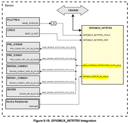
    Step2 : GPIO Interrupt Router configuration 

    In this step, we can configure GPIO interrupt Router input and output values.

    To configure these input and output values, typically we need to call a SCI client.

    Actually, the same step you are doing above by using the SCI client.

    So, here if you configure the ROUTER input as bank type, then you will get an interrupt for bank pins. 

    If you configure ROUTER   input as Pin type, you will get an interrupt for Pin type.

    Step3 : Interrupt configuration 

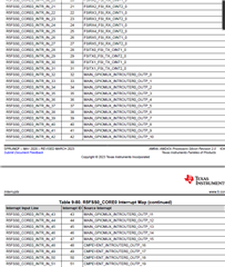
    Please look at the R5F interrupt table below. Here total 16 GPIO MUX Router output interrupts are routed to R5F cores.

    So, the interrupt number should be configured the same as the your  Interrupt Router output.

    Here you need separate interrupt callbacks for two pins. So, we need to select two interrupts for two GPIO pins.
    I hope above information will clarify your doubts .If your issue is Resolved please close the thread .
    Regards,
    S.Anil.
  • This is a nice summary for GPIO interrupts. Thank. I think now I got it. The confusing part is simply that there is no register to manage the GPIO interrupts.