This thread has been locked.

If you have a related question, please click the "Ask a related question" button in the top right corner. The newly created question will be automatically linked to this question.

MSPM0L1306: Digital input on PA2 not working after SET Digital Output PA20(SWCLK) with SWD disabled.

Part Number: MSPM0L1306
Other Parts Discussed in Thread: MSPM0L1105

My application circuit uses all pins on the MSPM0L1306, including the SWD pins. In order to utilize the debug pins as GPIO, the program delays a few seconds after boot, then sets the DISABLE bit in the SWDCFG register in SYSCTL along with the KEY. (...following instructions from section 2.4.1.4 in the Technical Reference Manual). 

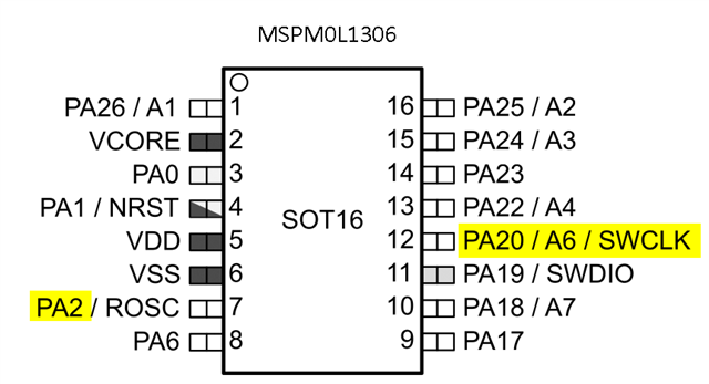
The debug pins work fine as GPIO. I am able to toggle PA19 and PA20 as Digital Outputs.

PA2 is also working as a Digital Input

The problem is... PA2 seems to stop working after the first time PA20 is set high. The PA2 input works fine throughout the program, as long as PA20 has not been set high in the program. After the first time PA20 is SET high, PA2 always reads 1. Clearing PA20 does not fix it. 

Edit: I tried re-initializing GPIO after every PA20 toggle in the program. The problem persists. 

  • Hi Dean,

    Ok, this strange.  Let me dig into this and I'll let you know what I find.

  •  Has anyone been able to reproduce this effect? I've tried replacing the chip with a new one, and also tried swapping it for a MSPM0L1105 with the same results. 

  • Hi Dean,

    I super apologize for the delay.  I didn't hear back from our designers regarding this so I will stop and try to duplicate right now.

    By chance, can you share your code so in case is does work for me I can compare with your code to see what is different.

  • Hi Dean,

    Can you share the specific instructions you use to disable the SWD pins and how you configure PA2 as input.  It appears I might be seeing the same issue. 

  • int main(void)
    {
        /* Power on GPIO, initialize pins as digital outputs */
        SYSCFG_DL_init();
        /* Configure PA1, PA19, PA20 after delay */
        delay_cycles(300000000);
        SYSCTL->SOCLOCK.SWDCFG = (SYSCTL_SWDCFG_KEY_VALUE | SYSCTL_SWDCFG_DISABLE_TRUE);
        SYSCTL->SOCLOCK.EXRSTPIN = (SYSCTL_EXRSTPIN_KEY_VALUE | SYSCTL_EXRSTPIN_DISABLE_TRUE);
        delay_cycles(100);
    
        //PA1-NRST GPIO
        DL_GPIO_initDigitalOutput(IOMUX_PINCM2);
        DL_GPIO_setPins(GPIOA, DL_GPIO_PIN_1);
        //DL_GPIO_enableOutput(GPIOA, DL_GPIO_PIN_1);
    
        //PA19-SWDIO GPIO
        DL_GPIO_initDigitalOutput(IOMUX_PINCM20);
        DL_GPIO_setPins(GPIOA, DL_GPIO_PIN_19);
        //DL_GPIO_enableOutput(GPIOA, DL_GPIO_PIN_19);
    
        //PA20-SWCLK GPIO
        DL_GPIO_initDigitalOutput(IOMUX_PINCM21);
        DL_GPIO_clearPins(GPIOA, DL_GPIO_PIN_20);
        //DL_GPIO_enableOutput(GPIOA, DL_GPIO_PIN_20);
    
        DL_GPIO_enableOutput(GPIO_PORT, DL_GPIO_PIN_1 |
                             DL_GPIO_PIN_19 |
                             DL_GPIO_PIN_20);
    
        delay_cycles(32000000);
    
        
        while (1) {
            
            
    //THIS WHILE LOOP WORKS UNTIL PA20 IS SET
            // WAIT FOR PA2 LOW
            while(DL_GPIO_readPins(GPIOA, DL_GPIO_PIN_2)){
                delay_cycles(100);
            };
    
    
    //THEN PA20 IS TOGGLED LIKE THIS
            DL_GPIO_setPins(GPIOA, DL_GPIO_PIN_20);
            delay_cycles(100);
            DL_GPIO_clearPins(GPIOA, DL_GPIO_PIN_20);
    
    
    //NOW PA2 ALWAYS READS 0, WHILE LOOP SHOOTS STRIGHT THROUGH, EVEN WHEN PA2 IS HIGH
            // WAIT FOR PA2 LOW
            while(DL_GPIO_readPins(GPIOA, DL_GPIO_PIN_2)){
                delay_cycles(100);
            };
            
            
        }     
        
    } 

    ... and here's PA2 config.