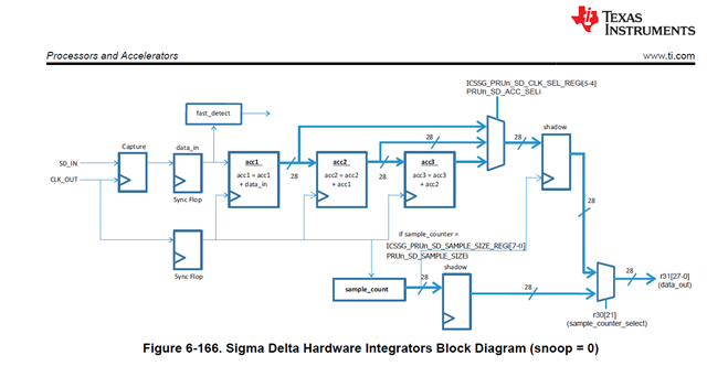
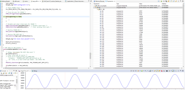
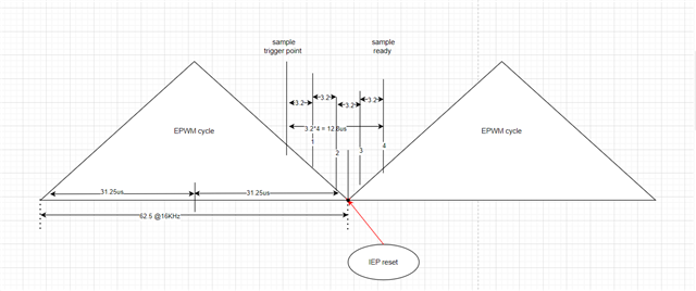
Part Number: MCU-PLUS-SDK-AM243X
I've added the following code:
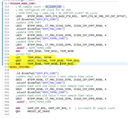
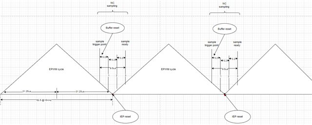
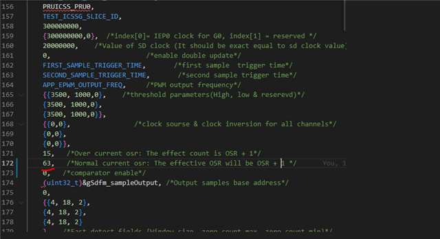
OSR is 64, normal current only.
16Khz
double sampling is on.
I'm having noisy samples every 26 or so samples.
Please advise
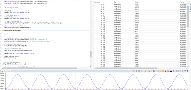
Part Number: MCU-PLUS-SDK-AM243X
I've added the following code:
OSR is 64, normal current only.
16Khz
double sampling is on.
I'm having noisy samples every 26 or so samples.
Please advise