This thread has been locked.
If you have a related question, please click the "Ask a related question" button in the top right corner. The newly created question will be automatically linked to this question.
I am working with the flashctl_multiple_size_write example and just adding some extra erase and write commands, to get the feel of the thing. I don't know what is happening, but sometimes I end up in the "You didn't provide a handler, stupid!" while loop stub.
How do I determine what interrupt put me there? I don't have the flashctl interrupt enabled.
Also, I keep getting "Sorry, you have too many breakpoints!" errors, when I have only specified one or two.
Hey Keith,
I am working with the flashctl_multiple_size_write example and just adding some extra erase and write commands, to get the feel of the thing. I don't know what is happening, but sometimes I end up in the "You didn't provide a handler, stupid!" while loop stub.
How do I determine what interrupt put me there? I don't have the flashctl interrupt enabled.
This is a very good question.
For any device supported by the LP-MSPM0G3507, use the following code:
/* * These are traps for debugging when you find that your code * ends up in the default handler for some unknown reason. * To keep the compiler from complaining, comment out the ones * below if you already have a working handler for that vector. * */ void NMI_Handler(void){ __BKPT(0);} void HardFault_Handler(void){ __BKPT(0);} void SVC_Handler(void){ __BKPT(0);} void PendSV_Handler(void){ __BKPT(0);} void SysTick_Handler(void){ __BKPT(0);} void GROUP0_IRQHandler(void){ __BKPT(0);} void GROUP1_IRQHandler(void){ __BKPT(0);} void TIMG8_IRQHandler(void){ __BKPT(0);} void UART3_IRQHandler(void){ __BKPT(0);} void ADC0_IRQHandler(void){ __BKPT(0);} void ADC1_IRQHandler(void){ __BKPT(0);} void CANFD0_IRQHandler(void){ __BKPT(0);} void DAC0_IRQHandler(void){ __BKPT(0);} void SPI0_IRQHandler(void){ __BKPT(0);} void SPI1_IRQHandler(void){ __BKPT(0);} void UART1_IRQHandler(void){ __BKPT(0);} void UART2_IRQHandler(void){ __BKPT(0);} void UART0_IRQHandler(void){ __BKPT(0);} void TIMG0_IRQHandler(void){ __BKPT(0);} void TIMG6_IRQHandler(void){ __BKPT(0);} void TIMA0_IRQHandler(void){ __BKPT(0);} void TIMA1_IRQHandler(void){ __BKPT(0);} void TIMG7_IRQHandler(void){ __BKPT(0);} void TIMG12_IRQHandler(void){ __BKPT(0);} void I2C0_IRQHandler(void){ __BKPT(0);} void I2C1_IRQHandler(void){ __BKPT(0);} void AES_IRQHandler(void){ __BKPT(0);} void RTC_IRQHandler(void){ __BKPT(0);} void DMA_IRQHandler(void){ __BKPT(0);}
Just in case anyone else stumbles on this thread looking for the same for devices supported by LP-MSPM0L1306. I'll add the equivalent for that device here:
/* * These are traps for debugging when you find that your code * ends up in the default handler for some unknown reason. * To keep the compiler from complaining, comment out the ones * below if you already have a working handler for that vector. * */ void NMI_Handler(void){ __BKPT(0);} void HardFault_Handler(void){ __BKPT(0);} void SVC_Handler(void){ __BKPT(0);} void PendSV_Handler(void){ __BKPT(0);} void SysTick_Handler(void){ __BKPT(0);} void GROUP0_IRQHandler(void){ __BKPT(0);} void GROUP1_IRQHandler(void){ __BKPT(0);} void TIMG1_IRQHandler(void){ __BKPT(0);} void ADC0_IRQHandler(void){ __BKPT(0);} void SPI0_IRQHandler(void){ __BKPT(0);} void UART1_IRQHandler(void){ __BKPT(0);} void UART0_IRQHandler(void){ __BKPT(0);} void TIMG0_IRQHandler(void){ __BKPT(0);} void TIMG2_IRQHandler(void){ __BKPT(0);} void TIMG4_IRQHandler(void){ __BKPT(0);} void I2C0_IRQHandler(void){ __BKPT(0);} void I2C1_IRQHandler(void){ __BKPT(0);} void DMA_IRQHandler(void){ __BKPT(0);}
Also, I keep getting "Sorry, you have too many breakpoints!" errors, when I have only specified one or two
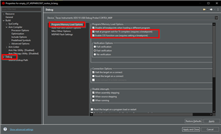
I've encountered this as well, as the MSPM0 only has 4 hardware breakpoints. I've never done a full audit of where all of these can be used, but I know at least 2 of these may be used up by the debug settings. See below in your project properties/debug settings):
I expect that if you do the following, CCS should dump the location of all currently enabled breakpoints:
Best Regards,
Brandon Fisher
It's either in IPSR or SCB->ICSR, I keep forgetting. [Ref DGUG (DUI0662B) Table 2-5 or Table 4-11.] The former is in the Core Registers display. The latter is at 0xE000ED04 (maybe somewhere in the Registers view, but I didn't find it.)
[Edit: It's in the IPSR low 6 bits. The ICSR has the next-pending number. Subtract 16 to get the IRQn number.]
That is also true Bruce.
Keith,
As Bruce said, this shows up in the core register view as well. That exception value in xPSR should correspond directly with the exception number from the table 3-3 (Interrupt and Exception Table) in the TRM.
Regards,
Brandon
Thanks, Bruce, at this point it was easier to add the stub. Turned out to be a brain-fart on my part. I forgot that flash write can only change a 1 to a 0, so I was getting ECC errors. This was actually a good learning experience, since I should put in a "magic" number anyway to see if I am wearing out the flash. I managed to trap the error, so that my MCU can warn me that the flash is worn out so we can replace the MCU on the production line. (I don't know that it will ever happen in practice, but if should use the poor MCU I am testing on, it could happen in a few weeks. 8^)
Brandon, since I have your attention, how do I specify the Map file to set aside a 64 byte sector for this persistent storage? I have tried this:
In a MSPM0g3507.cmd file in the root of the project, but it clearly pulled in the default cmd file, too so I got duplicate entry errors.
Here is the resulting map file:
MEMORY CONFIGURATION
name origin length used unused attr fill
---------------------- -------- --------- -------- -------- ---- --------
IntVectors 00000000 00001000 000000c0 00000f40 RW
FLASH 00000000 00020000 00000948 0001f6b8 R X
App_Write 00001000 00000040 00000000 00000040 RW
FLASH 00001040 0001efc0 00000000 0001efc0 R X
SRAM 20200000 00008000 0000026a 00007d96 RW X
SRAM 20200000 00008000 00000000 00008000 RW X
BCR_CONFIG 41c00000 00000080 00000000 00000080 R
BSL_CONFIG 41c00100 00000080 00000000 00000080 R
I don't think I am supposed to have 2 of every section. 8^)
Keith,
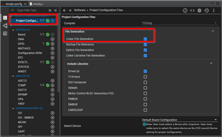
What version of the SDK are you using? Newer versions generate a linker file depending non the sysconfig settings, perhaps this is the output when you have a linker file and a generated linker file.
Can you go into sysconfig and disable linker file generation?
Best Regards,
Brandon Fisher
Thanks, that did it, I noticed that the project configuration seemed to be new with the sysconfig I got with Theia 1.3.1, but I never dove into it.
Here is my Map:
MEMORY CONFIGURATION
name origin length used unused attr fill
---------------------- -------- --------- -------- -------- ---- --------
IntVectors 00000000 00001000 000000c0 00000f40 RW
App_Write 00001000 00001000 00000000 00001000 RW
FLASH 00002000 0001f000 00000948 0001e6b8 R X
SRAM 20200000 00008000 0000026a 00007d96 RW X
BCR_CONFIG 41c00000 00000080 00000000 00000080 R
BSL_CONFIG 41c00100 00000080 00000000 00000080 R
I kept the size of the segment at 0x100, I was a little nervous going all the way down to 64 bytes. I was also a little worried about the "X's" in the Attributes, but I guess they are OK.
Now to move this to my production code.