This thread has been locked.

If you have a related question, please click the "Ask a related question" button in the top right corner. The newly created question will be automatically linked to this question.

MSP432E401Y: Incorrect ADC value on PK3.

Part Number: MSP432E401Y
Other Parts Discussed in Thread: SYSCONFIG

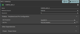
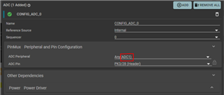
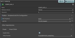
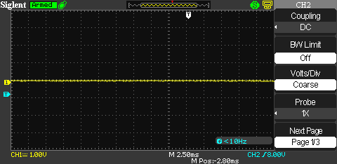
I have an MSP432E401Y FreeRTOS project that uses 4 different ADC channels. One of the ADCs (PK3) is monitoring the wiper of a potentiometer. The values read from that ADC seem to sporadically jump from 1.8V to 3.3V every few seconds regardless of the potentiometer's actual state. I've probed around the board with both an oscilloscope and a voltmeter. I have verified that pin 21 (PK3) is connected to the potentiometer with a very fine probe, and my instruments read the correct voltage. The other ADCs are working very well with a high level of accuracy. Does anybody know what might be causing this?

  • Hi,

      I have several questions:

      - Which Sample Sequencer are you using?

      - For experiment, what if you only sample one channel from PK3 instead of four channels. Can you repeat the same issue on PK3?

      - What if you swap the order of the sample inputs? For example, what happens if you make PK3 (AIN19) the first channel to be sample before the other three?

      - Can you repeat the same issue on the LaunchPad?

      - For experiment, not sure if you can use PK2 (AIN18) to sample the wiper? Does it produce the same issue? I just wanted to know if the issue is AIN19 specific. 

  • Hello again,

    1) I was using sequencer 0, but I've cycled through each. 

    2) I've commented out all code except for sampling on PK3, to no avail.

    3) Changing the order did not fix the issue.

    4) I just tried it on two LaunchPads, it behaves the same as it does on my custom board.

    5)   Weirdly, I can't get any ADCs on port K to function. I tried using my project's code as well as the "adcsinglechannel" example in CCS on both my custom board and the LaunchPads. If I use another port, it operates as expected.

    It is a little suspicious to me that I can't seem to get PK0-PK3 to function. Do I need to configure something out of the ordinary to unlock this port? I didn't see anything in the errata. 

  • Hi,

      Can you show your code? If you can't get any of the PKx pins to work then it is probably your pinmux configuration issue. 

  • Sure. I simplified the adcsinglechannel example to make it easier to read at a glance (the behavior still persists). 

    #include <stdint.h>
    #include <stddef.h>
    #include <ti/drivers/ADC.h>
    #include <ti/display/Display.h>
    #include "ti_drivers_config.h"
    
    void *mainThread(void *arg0)
    {
      ADC_init();
      Display_init();
    
      Display_Handle display = Display_open(Display_Type_UART, NULL);
      if (display == NULL) 
      {
        while (1);
      }
    
      ADC_Handle adc;
      ADC_Params params;
      ADC_Params_init(&params);
      adc = ADC_open(CONFIG_ADC_0, &params);
      if (adc == NULL) 
      {
        Display_printf(display, 0, 0, "Error initializing CONFIG_ADC_0\n");
        while (1);
      }
      uint16_t adc_raw;
      bool live = true;
      while (live == true)
      {
        int_fast16_t res = ADC_convert(adc, &adc_raw);
        if (res == ADC_STATUS_SUCCESS) 
        {
          uint32_t adc_uv = ADC_convertToMicroVolts(adc, adc_raw);
          Display_printf(display, 0, 0, "ADC raw result: %d\n", adc_raw);
          Display_printf(display, 0, 0, "ADC convert result: %d uV\n", adc_uv);
        }
        sleep(1);
      }
      ADC_close(adc);
    
      return (NULL);
    }
    

  • Is it possible that you are configurating for ADC1 instead of ADC0?

  • Sorry about that. I changed it to ADC0 and re-tested it on my devices just to make sure. Still not behaving properly. Even when PK3 is grounded, it's reading 1.2VDC.

  • Can you try the non-RTOS example. See below example from the SDK. Just wanted to rule out if the problem is rtos driver or pinux related. You can modify the example for PK3. 


  • I am not particularly familiar with nortos applications, so forgive me if I configure the example incorrectly. I've attached my code, a screenshot of my oscilloscope monitoring PK3, and the UART output I'm receiving from the LaunchPad.

    /* DriverLib Includes */
    #include <ti/devices/msp432e4/driverlib/driverlib.h>
    
    /* Standard Includes */
    #include <stdint.h>
    #include <stdbool.h>
    
    /* Display Include via console */
    #include "uartstdio.h"
    
    void ConfigureUART(uint32_t systemClock)
    {
        /* Enable the clock to GPIO port A and UART 0 */
        MAP_SysCtlPeripheralEnable(SYSCTL_PERIPH_GPIOA);
        MAP_SysCtlPeripheralEnable(SYSCTL_PERIPH_UART0);
    
        /* Configure the GPIO Port A for UART 0 */
        MAP_GPIOPinConfigure(GPIO_PA0_U0RX);
        MAP_GPIOPinConfigure(GPIO_PA1_U0TX);
        MAP_GPIOPinTypeUART(GPIO_PORTA_BASE, GPIO_PIN_0 | GPIO_PIN_1);
    
        /* Configure the UART for 115200 bps 8-N-1 format */
        UARTStdioConfig(0, 115200, systemClock);
    }
    
    int main(void)
    {
        uint32_t getADCValue[1];
        uint32_t systemClock;
    
        /* Configure the system clock for 120 MHz */
        systemClock = MAP_SysCtlClockFreqSet((SYSCTL_XTAL_25MHZ | SYSCTL_OSC_MAIN |
                                              SYSCTL_USE_PLL | SYSCTL_CFG_VCO_480),
                                              120000000);
    
        /* Initialize serial console */
        ConfigureUART(systemClock);
    
        /* Enable the clock to GPIO Port E and wait for it to be ready */
        MAP_SysCtlPeripheralEnable(SYSCTL_PERIPH_GPIOK);
        while(!(MAP_SysCtlPeripheralReady(SYSCTL_PERIPH_GPIOK)))
        {
        }
    
        /* Configure PE3 as ADC input channel */
        MAP_GPIOPinTypeADC(GPIO_PORTK_BASE, GPIO_PIN_3);
    
        /* Enable the clock to ADC-0 and wait for it to be ready */
        MAP_SysCtlPeripheralEnable(SYSCTL_PERIPH_ADC0);
        while(!(MAP_SysCtlPeripheralReady(SYSCTL_PERIPH_ADC0)))
        {
        }
    
        /* Configure Sequencer 3 to sample a single analog channel : AIN0 */
        MAP_ADCSequenceStepConfigure(ADC0_BASE, 3, 0, ADC_CTL_CH0 | ADC_CTL_IE |
                                     ADC_CTL_END);
    
        /* Enable sample sequence 3 with a processor signal trigger.  Sequence 3
         * will do a single sample when the processor sends a signal to start the
         * conversion */
        MAP_ADCSequenceConfigure(ADC0_BASE, 3, ADC_TRIGGER_PROCESSOR, 0);
    
        /* Since sample sequence 3 is now configured, it must be enabled. */
        MAP_ADCSequenceEnable(ADC0_BASE, 3);
    
        /* Clear the interrupt status flag.  This is done to make sure the
         * interrupt flag is cleared before we sample. */
        MAP_ADCIntClear(ADC0_BASE, 3);
    
        /* Sample AIN0 forever.  Display the value on the console. */
        while(1)
        {
            /* Trigger the ADC conversion. */
            MAP_ADCProcessorTrigger(ADC0_BASE, 3);
    
            /* Wait for conversion to be completed. */
            while(!MAP_ADCIntStatus(ADC0_BASE, 3, false))
            {
            }
    
            /* Clear the ADC interrupt flag. */
            MAP_ADCIntClear(ADC0_BASE, 3);
    
            /* Read ADC Value. */
            MAP_ADCSequenceDataGet(ADC0_BASE, 3, getADCValue);
    
            /* Display the AIN0 (PE3) digital value on the console. */
            UARTprintf("AIN0 = %4d\r", getADCValue[0]);
    
            /* Delay the next sampling */
            MAP_SysCtlDelay(systemClock / 12);
        }
    }
    

  • On the below line, you need to change to ADC_CTL_CH19 which is PK3. Please also try it on other channels like PE3/PE2 or PK2/PK1 to get a good reference for comparison. 

    /* Configure Sequencer 3 to sample a single analog channel : AIN0 */
    MAP_ADCSequenceStepConfigure(ADC0_BASE, 3, 0, ADC_CTL_CH19 | ADC_CTL_IE |
    ADC_CTL_END);

  • Thank you.

    I've tried AIN16-19, and they all appear to work properly in the nortos example. Their readings roughly match my oscilloscope. Do you know how I might fix this for the freeRTOS implementation? 

  • Can you try the TI-RTOS version of the example so we know if it is a general sysconfig pinux issue or only specific to FreeRTOS. I suppose you will see the same result. The TI-RTOS drivers abstract users from the hardware using the .sysconfig but it is supposed to do all the ADC initialization much the same as the non-rtos version under the hood. 

  • Sure!

    I have tested the TI-RTOS version now, and it has the same issues as the FreeRTOS. 0VDC on PK3, and it reads ~1200000 µV.

  • How should I move forward with this issue? 

  • I've spent a little time today trying to get the "fixed project" to compile, but I've been running into a lot of linking issues and whatnot. I'm wondering if the fix is a little outdated or something. I'll try to sort it out and then convert the project to freeRTOS. 

  • Good morning,

    I still can't seem to get Chris Sterzik's workaround to build properly. Could you see if you're able to get his project to build properly as a sanity check? 

    Also, I've been comparing Chris Sterzik's workaround to what is contained within the simplelink msp432e4 sdk driver files on my system. It looks like the changes Sterzik made in the workaround were added into the sdk at some point?

    For example, line 249 in his file called ADCBufMSP432E4.h is implemented in ADCBufMSP432E4.h in my simplelink SDK on line 307. I also see his edit to ADCBufMSP432E4.c on line 64 has been shipped with my SDK's ADCBufMSP432E4.c on line 49.

    The only real difference I can find is in the workaround's MSP_EXP432E401Y.c on line 152. I've tried adding that to my project, but it doesn't seem to fix the behavior. 

    Any help or guidance would be appreciated.

  • Hi Daniel,

      I wish I could provide better guidance but I'm not familiar with the intricacy of MSP432E SimpleLink myself. What I found is that the two non-buffer version of the files in C:\ti\simplelink_msp432e4_sdk_4_20_00_12\source\ti\drivers\adc do not have the same changes as the buffered version. I think it may be easier to rebuild the library after the changes. This link has the instructions on how to rebuild the library. https://dev.ti.com/tirex/explore/content/simplelink_msp432p4_sdk_3_40_01_02/docs/simplelink_mcu_sdk/Users_Guide.html#rebuilding-drivers

  • Fair enough. If I manage to fix the issue, I'll do my best to post it here just in case somebody else runs into the same issue.

    Thank you for the resources!

  • Hi Daniel,

      I hope the information provided is allowing you to create a workaround. I will close the thread for now. If you have any update, you can write back to this thread and it will change the status to OPEN.