This thread has been locked.

If you have a related question, please click the "Ask a related question" button in the top right corner. The newly created question will be automatically linked to this question.

TM4C129XNCZAD: Connecting to my device with LaunchPad Evaluation Kit vs Developer Kit

Part Number: TM4C129XNCZAD
Other Parts Discussed in Thread: EK-TM4C1294XL

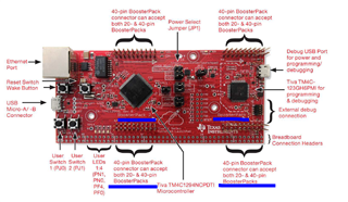
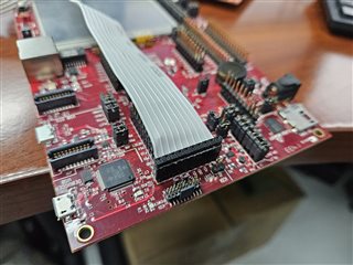
I am thinking somebody has asked a question like this before, but I searched and didn't find anything.  I've been using the TM4C129X Development Board to interface with our controller board and update firmware.  Now I'm trying to use the TM4C1294 Connected Launchpad Evaluation Kit (EK-TM4C1294XL).  I know which connector to use and the proper orientation for the interface cable to connect to our board.  How do I know which connector to use and the proper orientation on the Evaluation Kit board?

  • Hi,

      If you are referring to the two boosterpack connectors then they are described in the user's guide. The one on the right is the boosterpack 1 connector and the one one the left is the boosterpack 2 connector. 

    The user's guide also shows the pin name and number of each bootsterpack header pin. See below screenshot. You can find the full detail in the user's guide. 

    For example the A1 header pin 1 is 3.3V and pin 2 is PE4 and pin 3 is PC4. If you turn to the back of the LaunchPad you will see the silkscreen matching the names. 

  • That's great.  Thank you very much.  Now if only the development kit board (with a display) used the same terminology so I could easily transfer from one to the other.  The cable that the previous developer set up is a 10 pin cable.  Our development kit board has 3 connectors with 2 rows of 10 pins on each, and another connector with only 1 row of 10 pins.  So the way I'm counting it, that makes 7 possible places to connect my cable.  Fortunately I have a picture showing me where to connect my cable.

    So how do I know how to connect my cable on the small evaluation kit board shown in the photo you posted?  It has 4 connectors with 2 rows of 10 pins each, so that makes 8 possible connections.  If I add polarity, there are 16 possible ways to connect my cable.  What are the chances I get it right?  I very much appreciate your help.

  • Here are some pictures showing my current connection.

  • I think we are talking about different things. I think what you are trying to do is to use the onboard ICDI to debug out another board. Is that correct? Refer to the DK-TM4C129X user's guide. https://www.ti.com/lit/pdf/spmu360

    If this is what you want with EK-TM4C1294XL as to use its onboard ICDI to debug out another board, you can refer to this app note https://www.ti.com/lit/pdf/spma075 section 4.8. 

  • I have never tried to do any debugging, I'm just trying to program our controller boards (update firmware).  I guess that requires the same interface as debugging, right?  Is there a different way to update our firmware & program our boards?  I'm totally new to this TI product line.

    I am looking at the documentation.  I just wonder why this can't be a little easier.  I never faced this kind of confusion with previous microcontrollers I worked with.  Wouldn't it be simple to label the interfaces and design connecting interfaces in such a way that it's very clear?

  • Hi,

      All the connectors and interfaces are shown in the user's guide. There is silkscreen on the board for each connector. For example, you will see U22 for Debug USB port. You see U6 if you want to use an external debug probe. The X1 silkscreen is also described in the user's guide. You can refer to the ICDI section on how to use U6 if you have an external debugger or to use X1 if you want to debug out another board using the onboard ICDI 

  • Charles, thank you again for your help.  There must be something I'm missing.  I looked at section 4.8, as you suggested--thank you for pointing out the exact location in the document.  But I'm wondering why I have to remove surface mount resistors and connect individual wires to my board.  We are not in the R&D phase, we are in the production phase.  Our equipment is mounted at the top of a tank, so I need to take my laptop up there, connect a cable, and program the board when I update firmware.  With the development kit board, it's bulky, but at least it can still be done in a matter of minutes.

    Is the solution for me to buy more of the older development kit boards?  How are people programming devices during factory production?  Why is it that the development kit board apparently came ready to do this task, but now I have to get out a soldering iron and hook up wires to do this?

  • Hi Mark,

     I'm in no position to comment on your company's prior business decision for using the DK-TM4C129X EVM as a debug probe to debug/program other boards. I can only tell what most customers do. When a custom board is designed, a standard JTAG connector is mounted on the board so any supported external debug probe can be used to debug and program the board. An example low cost debug probe would be XDS110 and XDS200.  It is certainly possible to use the ICDI on the EVM as a debug probe to debug/program another board. This is apparently the case as you have described your systems and the picture you attach. Nothing wrong with that as it has worked for you until now. People use this solution because it is a free solution because they don't need to buy another standalone debug probe once they purchase the EVM for their initial firmware development. The EVM comes with a onboard ICDI emulator.  The ICDI solution is not as robust for several reasons.

      First, the J3 connector that you attach the cable to debug out another board is NOT a standard JTAG connector (Arm 10pin or 20 pin JTAG connector). Refer to section 3 of this app note. if you want to be familiar with the JTAG connectors. https://www.ti.com/lit/pdf/spma075. What this means is that the cable you attach is a custom cable.

     Second, it is bulky compared to a standalone debug probe. If you compare the size of the EVM and a debug probe like XDS110/XDS200, it is much bulkier.

     Third, purchasing another EVM will not be any cheaper. If the EVM is still for sales, it would have been several hundreds of dollars which is much more expensive than a low cost probe like XDS110 ($135).

     Fourth, the DK-TM4C129X is already obsolete. It is no longer in production. 

    Since the DK-TM4C129x is no longer for sales, your only option to continue using ICDI debug probe is to use the EK-TM4C1294XL LaunchPad. The LaunchPad, like the EVM has an unpopulated X1 footprint that you can use to debug out other boards using its onboard ICDI. Again, the X1 is not a standard JTAG connector. It is also not compatible with the J3 on the EVM  board. The custom cable you design will not work on X1 of the LaunchPad. You would need to design a new cable as described in section 4.8 of the app note I mentioned. 

     The LaunchPad ($25) is a low cost board to quickly allow customers to start software development and evaluation. You would just plug in a USB cable to U22 Debug USB port and can quickly debug/program the firmware on the target chip. The debug out capability is only a secondary benefit. Most customers ultimately will install a JTAG connector on their final boards so they can freely choose any debug probe of their liking. 


  • Thank you very much.  This is the information I needed.  I was not involved with the design of our board, I'm just now taking over the firmware (I've never done any hardware design).  But we are about to do a board rev, and now I know we need to add a standard JTAG connector.  I will make sure that gets done!

    Again, I appreciate your help.  When I did my first big project we used the Motorola HC12 microcontroller, and they provided telephone support--someone to talk to.  I've been outside the industry for a while, and I'm just getting back in. I don't know if any companies still offer that kind of telephone support.  It's a little frustrating being forced to type everything out and then wait for a reply, not knowing when you'll get one.  But now I have my answer, and I'm very thankful.