This thread has been locked.

If you have a related question, please click the "Ask a related question" button in the top right corner. The newly created question will be automatically linked to this question.

TMS570LC4357-EP: To read the value of an ECAP-input, must the signal go to 2 CPU-pins?

Part Number: TMS570LC4357-EP

I am trying to use 3 ECAP inputs to measure a motor Hall-feedback timing, but on each hall-edge transition, I need to read the logic-value of the input. In order to use ECAP, it looks like I need to assign the pin-mux as an ECAP (not an N2HET), but I do not see in the ECAP registers the ability to read the logic value present on the ECAP input. Does this ECAP input also need to be routed to a second GPIO/N2HET input in order to read the logic value?

Thanks,

Jim

  • Hi Jim,

    Yes, you are right. The pin can only do one functionality, that means if we enable eCAP functionality to a pin then other functionalities will get disable on the corresponding pin.

    Does this ECAP input also need to be routed to a second GPIO/N2HET input in order to read the logic value?

    Yes, this is one way to do it.

    However, i want to suggest you one more method, which i never tested but it should work. The advantage is that this method doesn't require any additional pins but drawback is that it cannot be used for high frequencies.

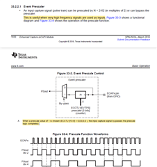
    1. First of all disable the pre-scaler because this will change the waveform.

    So, to get original waveform to the eCAP module we should disable the pre-scaler.

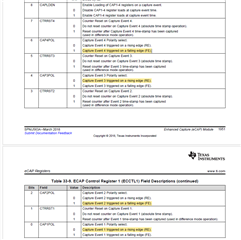
    2. Now configure the capture polarities as below

    CAP1- Raising

    CAP2- Falling

    CAP3- Raising

    CAP4- Falling

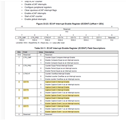
    3. Now enable the capture interrupts for all the four captures

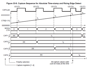
    That means, we will get CAP1 interrupt for first raising edge (Low to High transaction) of the input, CAP2 interrupt for first falling edge (High to Low transaction) of the input, CAP3 interrupt for second raising edge (Low to High transaction) of the input and CAP4 interrupt for second falling edge(High to Low transaction) of the input. And this sequence will continue every time.

    4. Now just assume one "Input_Value" Flag was there to indicate the input status.

    And now what i will do is that, whenever i received either CAP1 or CAP3 interrupt then in interrupt handler i will set "Input_Value" as 1 because CAP1 or CAP3 interrupt is a raising edge interrupt and input value will be shifted from low to high that means my input waveform is at logic high now. In contrast to this whenever i received CAP2 or CAP4 interrupts then in interrupt handler i will reset "Input_Value" as 0 because CAP2 or CAP4 interrupt is a falling edge interrupt and input value will be shifted from high to low that means my input waveform is at low now.

    So now i will use this "Input_Value" in the code and will do the necessary operations if required.

    --
    Thanks & regards,
    Jagdish.