This thread has been locked.

If you have a related question, please click the "Ask a related question" button in the top right corner. The newly created question will be automatically linked to this question.

RM57L843: ADC Issue

Part Number: RM57L843

Hi team,

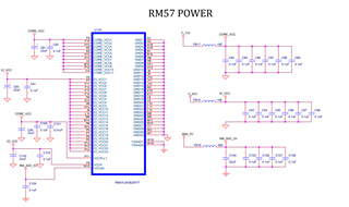
    In our custom board we use RM57L843, we use 10 ADC input channels all inputs are from 2nd order low pass filter. when we give 5V to the ADC inputs, values are fluctuating randomly. In Schematic we checked the voltage at R836 by using both multimeter and DSO the input voltage is constant. 

 adc.pdf

Thanks,

Regards,

Veerappan PA.

  • Hi, 

      When we give the voltage directly  to controller side by removing R836 and without giving +15V and -15V of OP-AMP at that time ADC will read correctly. When we power on the OP-AMP +15V and -15V again the voltage is fluctuating even when we give directly to controller side.

    Thanks,

    Regards,

    Veerappan PA.

  • Hi Veerappan,

    I don't see any issues in your circuit:

    Your op-amp gain set to 1 and cutoff frequency was set to 320Hz approximately.

    values are fluctuating randomly.

    How much fluctuation you are getting,

    What is your input applied voltage and what is the fluctuation you are getting?

    --
    Thanks & regards,
    Jagadish.

  • Hi jagadish gundavarapu,

         How much fluctuation you are getting?

                  When I give 4.9V, it reads 2V, 2.3V, 4V, 4.5V, 1V like this.

        Now the issue is solved. What we done is instead of giving +15V and -15V to OP-AMP we give +15V and 0V. But previous one +15V and -15V is also correct one why ADC will not read correct values?

    Thanks,

    Regards,

    Veerappan PA.


  • Now the issue is solved. What we done is instead of giving +15V and -15V to OP-AMP we give +15V and 0V. But previous one +15V and -15V is also correct one why ADC will not read correct values?

    It is working after you are changing the op-amp supplies, means it should not be any issue from controller ADC.

    When I give 4.9V, it reads 2V, 2.3V, 4V, 4.5V, 1V like this.

    This much of voltage variation will not get from controller, if the input supply is constant.

    both multimeter and DSO the input voltage is constant. 

    Multimeter will do some avg, i mean it won't give you an instant voltage every time. You should measure with oscilloscope to observe the exact variation in the input.

    --
    Thanks & regards,
    Jagadish.

  • Hi jagadish gundavarapu,

           We use 4 channel external ADC also, at the time of giving +15V and -15V to OP-AMP  the external ADC is reads correct value. But controller value fluctuating.

           We checked using oscilloscope the input voltage to the ADC is constant.   

    Thanks,

    Regards,

    Veerappan PA.

  • Hi Veerappan,

    In your schematic, i couldn't see VCCAD and VSSAD pins. I could only see VREFHI and VREFLO pins.

    What is the supply voltage you connected to the VCCAD and VSSAD?

    If you are trying to measure upto 5v with ADC then VCCAD and VSSAD should also supplied with 5v.

    And remember one thing that VREFHI should not be more than VCCAD, i mean we should not give VCCAD with 3v and VREFHI with 5v.

    --
    Thanks & Regards,
    Jagadish.

  • Hi jagadish gundavarapu,

    We give 5V for VCCAD, the power of controller is shown below. And our VREFHI and VCCAD are 5V.


    Thanks,

    Regards,

    Veerappan PA.

  • Hi Veerappan,

    We give 5V for VCCAD, the power of controller is shown below. And our VREFHI and VCCAD are 5V.

    In that case, everything looks fine for me.

    I don't have this setup with me as well to test at my end.

    --
    Thanks & Regards,
    Jagadish.