Part Number: MSPM0L1306
Hi Team
I have trimmed my clock from 32 MHz to 24 MHz. How can I allocate all the peripherals (UART-LIN, Timer) to operate at 24 MHz. Can you please help me with this ASAP.
This thread has been locked.
If you have a related question, please click the "Ask a related question" button in the top right corner. The newly created question will be automatically linked to this question.
Part Number: MSPM0L1306
Hi Team
I have trimmed my clock from 32 MHz to 24 MHz. How can I allocate all the peripherals (UART-LIN, Timer) to operate at 24 MHz. Can you please help me with this ASAP.
Hi Team,
Why I asked is because it's in a 24MHz clock, but when the UART is transmitting, it goes to 32 MHz, then comes back to 24MHz. However, I want it to remain at 24 MHz. What should I do. Can anyone please help regarding this ASAP.
Hi Zoey,
Thank you so much for the reply
I have configured it as 32 MHz
I followed this link for trimming
e2e.ti.com/.../mspm0l1306-in-mspm0l1306-i-need-to-convert-the-clock-frequency-from-32mhz-to-24mhz

Hi,
Can you change the clock source to SYSOSC to have a try?
And I will have the same test from my side
B.R.
Zoey
Hi Zoey,
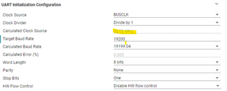
In the clock source, we have three options:
Hi,
Sorry for late reply, I am quite busy this afternoon, I will try to answer ASAP.
B.R.
Zoey
Hi,
Thank you for your reply,
I waiting for your response regarding the clock source
Hi,
Sorry for reply,
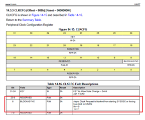
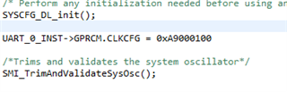
Please add this code line: UART_0_INST->GPRCM.CLKCFG = 0xA9000100;

B.R.
Zoey
Hi Zaoey
Thank you so much for the reply
I am using this example code for trimming. I have added the last line, and it is working perfectly now. However, I am not getting proper data in RX after doing this. What could be the reason.

Hi zaoey,
Can you Please reply for this ,we are planning to complete this by tomorrow
Hi Zaoey,
I am encountering a new error when implementing the following:


can you Please help regarding this ASAP
Hi,
I will check tomorrow morning, as it is evening in China.
Can you send your code again.
B.R.
Zoey
,Hi Zaoey,
I have attached the code for your reference. Please help me with it. Tomorrow, it will be more helpful.
Hi Santhosh,
Sorry for late reply.
The wrong data is because your clock is changed into 24M not 32MHz. As the hardware sample is still 32MHz. So if you want to transmit like 0x5A, every bit stay longer timer than initial 32M setting.
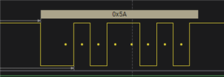
For example, the baud rate is 9600bit. The transmit waveform using 24MHz is as follows:


The actual output baud rate is not 9600. This is due to the clock change, but the UART hardware still processes and sends it as 32MHz.
So if you want to send the right 9600 baud rate, you have to change the baud rate to 9600*32(depends on the clock you choose, if MFCLK then it will be 4)/24 = 12800.

And then the result is:

Have a nice weekend~
Zoey
Hi Zoey,
Thank you so much for the reply.
So, this change is not required: UART_0_INST->GPRCM.CLKCFG = 0xA9000100, right?
Because if I add this change, I am getting this issue:
CORTEX_M0P: Error: (Error -1001 @ 0x0) Requested operation is not supported on this device. (Emulation package 9.13.0.00201)
Without adding this, I am getting data, but I am seeing fluctuations on the scope. I have attached a video for your reference.
can you Please help me regarding this Please
Hi
You have to add this, if not use this sentence, the UART will make the SYSOSC back to the 32MHz.E2E_UART_24 MHz trim using FCC_dichotomy.zip
Can you make my code to have a try?
B.R.
Zoey
Hi Zoey,
Thank you so much for your reply and patience.
Currently, there is no fluctuation in scope, but I am not receiving any data from UART. The baud rate is 10417, according to your calculation, but it should be 13889.
We are almost there, but I am making some mistakes that I am unable to figure out


Hi Zoey,
Thank you so much. Finally, I got it; the jumper was in loose connection.
Thank you very much for your help
Happy weekend