This thread has been locked.

If you have a related question, please click the "Ask a related question" button in the top right corner. The newly created question will be automatically linked to this question.

TM4C129XNCZAD: USB OTG kill the microcntroller

Part Number: TM4C129XNCZAD

Hi,

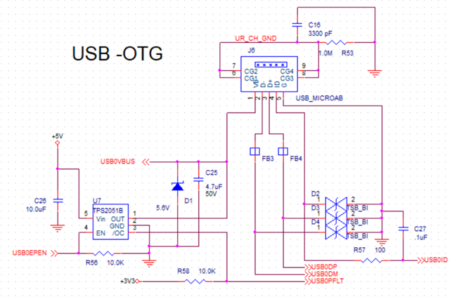
I am utilizing the TM4C129XNCZAD microcontroller, employing the OTG port in my design. Strangely, upon connecting the microcontroller to the computer, it gets damaged. While the port isn't intended for direct connection to a PC, we have another port equipped with an FTDI chip to facilitate connection of the USB device to the computer. However, if the client mistakenly connects the OTG port to the computer, it results in the microcontroller being damaged.

Do you have any insights into why the microcontroller is being damaged in this scenario? Additionally, what measures can be taken to safeguard the microcontroller from such damage?

Thank,

Mohammed

  • Hi,

    Do you have any insights into why the microcontroller is being damaged in this scenario? Additionally, what measures can be taken to safeguard the microcontroller from such damage?

    I'm not sure why the chip is damaged. I don't really spot anything wrong on your schematic. You do have a 100ohm current limiting resistor on the ID input.  I also see the protection diodes. Here are some things to check:

    - You seem to suggest that if the MCU USB is first connected to the FTDI before connecting tot the PC then there is no issue. Is that correct?

    - When you said the device is damaged, do you know what specifically is damaged?

    - Can you do a resistance check on the pins? Do you see any shorts? -

    - Can you repeat the same problem on another PC?

    - Can you repeat on a LaunchPad?

    - How about a different USB cable?

    - Can you monitor the USB signals on a scope when you plug the device into the PC? Do you see any over-voltage? 

    - Please bear in mind that PB0 is only 3V tolerant. Do you see any over-voltage on this signal. This is the only thing I can think that may lead to chip damage if the ID input exceeds 3.3V. 

    4.3.3 USB OTG
    TM4C129x devices that support USB OTG mode include the signals for USB Device mode, signals for
    USB Host mode and an additional signal USB0ID located on pin PB0. This USB ID signal is the 5th pin
    found on a USB micro-AB connector. If a micro-A cable end is plugged into this connector, the ID pin on
    the cable is tied to ground causing the TM4C129x device to operate as a USB host. If a micro-B cable end
    is plugged into the USB connector, the ID pin is left floating. In this case, the TM4C129x device's internal
    pull-up on the USB0ID signal causes the controller to operate in device mode.
    In order to limit damage from ESD events, a 100Ω resistor should be placed in series between the ID pin
    on the USB connector and USB0ID(PB0) on the microcontroller.
    To support full USB OTG negotiation using the SRP and HNP protocols, VBUS from the USB connector
    must be directly connected to USB0VBUS(PB1) of the microcontroller without a series resistor in between.
    In this case, USB0VBUS should be connected to an ESD suppressor such as a TVS diode, or ESD
    resistant VBUS switch.