This thread has been locked.

If you have a related question, please click the "Ask a related question" button in the top right corner. The newly created question will be automatically linked to this question.

LP-AM243: MCSPI communication with PCI11400 bridge

Part Number: LP-AM243
Other Parts Discussed in Thread: SYSCONFIG

Hello,

I am trying to implement the communication between LP-AM243 and Microchip's PCI11400 PCI-SPI bridge.

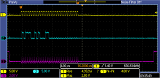
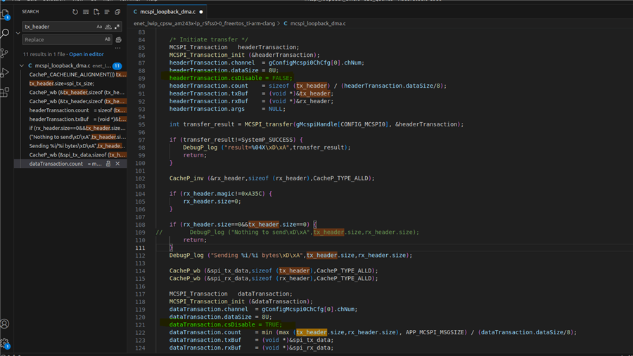
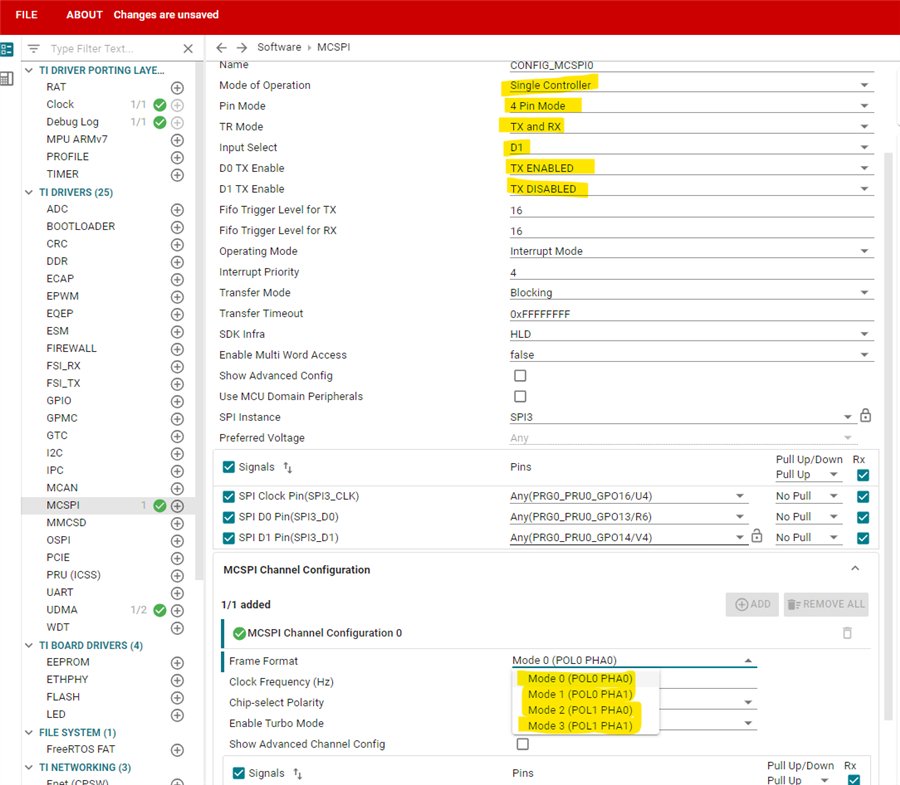
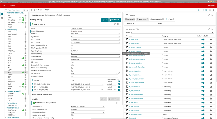
The bridge is host only, and is verified to output data (I can see waveforms on oscillograph). LP-AM243 connected to PCI11400 through SPI3 pins (J1.13, J2.6, 12,14 even though CS apparently is not needed). Software on the Texas side uses parts of mcspi_loopback_dma example, and also works if the device is configured in host mode - once again, I've seen waveforms. However, if the configuration is changed for device mode, transmission does not occur.

While I can see CLK signal oscillating, the transfer does not happen. Additionally, if I try to change the configuration for polling and step over the program, the interrupt never happens and CSL_MCSPI_IRQSTATUS is always zero.

I feel like I am missing some configuration details, but I've checked out most every aspect.

Could someone please point me in the correct direction?


Best regards,

Gennadii.

  • Hi Gennadii,

    Thanks for your question.

    I am going to look through this after sometime and follow up with you.

    Regards,

    Vaibhav

  • Hello Gennadi,

    I have few follow up questions.

    1. Can you please forward me the Microchip's PCI11400 PCI-SPI bridge datasheet so that I can have a look at it if needed later in the debug.
    2. Are you currently using the latest SDK which is SDK release 09.01.00.41 or previous release?
    3. If the answer to Question 2 is YES, then which drivers are you currently using HLD or LLD?
    4. Please correct my understanding, I think you are using SoC_SPI3 peripheral for your application.

    Looking forward to your response.

    Regards,

    Vaibhav

  • Hello, Vaibhav.

    1. Unfortunately, it appears I can not upload the datasheet, as it is NDA only. However, I have attached a screenshot of the waveform for you to confirm it.

    2. Yes, SDK 09.01.00.41 is used.

    3. I am using HLD.

    4. Yes, the datasheet refers to it as 'MAIN MCSPI module instance 3'.

  • Hello Gennadi,

    Thanks for your response.

    It would be nice to get the project file you have created with SoC_SPI3. I would need to look at the code and apart from this I would also like to know about the hardware connections via jumper cables/wires which you made from SoC_SPI3 to the Peripheral.

    Looking forward to your response.

    NOTE: Let me know if you are comfortable sharing the project file here or over mail, accordingly you can send.

    Regards,

    Vaibhav

  • Hello, Vaibhav.

    Please provide an email to send project files to.

    Best regards,

    Gennadii.

  • Hello Gennadii,

    Please check your inbox, you should have received my mail by now.

    Apart from sending the project file, I would like you to tell me the pre setup you have done, for example have you done SoC Initialization via SBL or some other way?

    Looking forward to your response.

    Regards,

    Vaibhav

  • Hello Gennadi,

    I had a chance to go through the code you sent over mail.

    Can you please explain the reasoning behind setting the first CS Disable to False and the subsequent CS Disable to True ?

    I believe both should be set to True.

    Also could you explain what is the first SPI Transaction doing and what the second one is doing.

    Regards,

    Vaibhav

  • Hello,

    as  i have mentioned in a email, this piece is a leftover from the debug. I have tried both with CS Disable set to true and false, and, as I've been sending the code to you, I didn't completely replace the variable.

    The first transaction is supposed to transcieve the header with sizes of a main payload, while the second transaction transcieves the data itself.

    Additionally, yesterday I've managed to verify the same communication for the different hardware solution as a secondary device.

    Best regards,

    Gennadii.

  • Hello Gennadii,

    Thanks for your response.

    I will be taking a look at this in sometime and update you in few business days.

    Regards,

    Vaibhav

  • Hi Gennadii,

    Thanks for your patience.

    I would say that the code you have written is correct.

    The only concern I would have as of now, is to check if the SysConfig settings are done correctly for you. (NOTE: The project you sent me over mail does not contain the SysConfig settings.)

    I want you to make sure that the MCSPI peripheral actually supports the Mode 0 operation which is default Frame Format.

    In case it does not, then there are four different frame formats you can choose from as highlighted at the bottom of the attached screenshot.

    Moreover, I want you to make sure that the connections are correct and the wires are not faulty. For example with the above configuration as highlighted on top of the attached screenshot, I would simply connect my Controller's D0 line to Peripheral's MOSI line and Controller's D1 line to Peripheral's MISO line.

    Can you please confirm the above information?

    Looking forward to your response.

    Regards,

    Vaibhav

  • Hello, Vaibhav.


    First of all, why would you configure AM243x in the controller mode? AM243x is supposed to work in device mode, which is set up as expected (see attached screenshot).

    I've took measurements with oscilloscope on the LP pins, therefore there is no chance for wire failures. Additionally, as I have mentioned before, if I switch AM243x to the controller mode, I will see the data output on the very same wires.

    Best regards,

    Gennadii.

  • Hi Gennadii,

    Thanks for your response.

    Please expect responses in sometime.

    Regards,

    Vaibhav

  • Hi Gennadii,

    Your SysConfig configuration looks good along with the code as well.

    Can you provide a sleep/delay of about 1000 ms before initiating transfer from Peripheral back to the Controller and let me know the results?

    Regards,

    Vaibhav

  • Hello, Vaibhav

    I've added a loop counting to 10,000,000 just after drivers initialization and it changed nothing:

        Drivers_open();
        Board_driversOpen();
        for (int i=0;i<10000000;i++);
        enet_lwip_initialize(NULL);
        lwip_start();
    

    Also, I want to notice that transmission by the host is performed constantly in a loop, with the same pattern - so whatever you see on the oscilloscope screenshot is not just a single burst.

    Best regards,

    Gennadii.

  • Hello Gennadii,

    Thanks for your response.

    Please allow me some more time to look into this and provide a response as I am in full day trainings.

    Regards,

    Vaibhav

  • Hello Gennadii,

    Thanks for your patience.

    Working problem of a specific protocol lets say MCSPI or I2C in Peripheral/Slave mode has been seen earlier as well.

    I would request you to check my latest response on this thread: https://e2e.ti.com/support/processors-group/processors/f/processors-forum/1353292/am62a7-am62a7-am62a7-q1-mcu-i2c-slave-test/5235344#5235344

    NOTE: Look for the highlighted thread, it is marked a bold green vertical line on the left hand side.

    Based on my response, you can check the places where IPC Sync Mechanism is introduced, so, can you to follow the same approach in your case as well.

    Looking forward to your response.

    Regards,

    Vaibhav

  • Hello, Vaibhav.

    I apologize for the delay. Because of the severity of the issue, I had to run multiple tests to verify your solution.

    With this, I can positively confirmed that the suggested method resolves the problem.

    Thank you for your help.


    Best regards,

    Gennadii.