Other Parts Discussed in Thread: MSPM0G3507, , SYSCONFIG
Hi All,
Currently, I am delving into the study of TI’s MSPM0G3507 MCU for an upcoming project that I will be actively involved in. To facilitate my understanding, I am utilizing the LP-MSPM0G3507 Evaluation Kit to familiarize myself with TI’s ARM MCU architecture and IDE platform. Furthermore, I am exploring example projects to gain insight into the peripherals.
Beginning with the GPIO toggle output example, I successfully observed the output toggling. Subsequently, I progressed to studying timers and attempted the “timg_32bit_timer_mode_pwm_edge_sleep” example to test the PWM signals generated using timer-related examples from mspm0_sdk_1_30_00_03.
However, upon building and debugging the project in CCS Studio, I encountered an issue where the code entered the “Default_Handler” when the “DL_TimerG_reset” function was called.


After further investigation, I found a suggestion in TI E2E design support. I implemented the suggested code to determine the trigger for the Default Handler event, only to discover that the code actually entered the “Hardfault_Handler” instead.
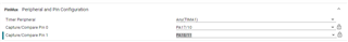
So I used SysConfig file in the project, changed the current TIMG12(32bit) timer into TIMA1(16bit) and changed the 32bit PWM Period value into 16-bit Period value.


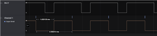
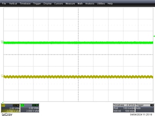
And I rebuilt and debugged the project again. But this time, the code didn’t enter the Hardfault_Handler but I couldn’t see any signals generated from both CCP channels, PA10 and PA11 pin on the Eval Kit when I probed these signals.
I have also attempted another pwm_edge example, but the outcome was largely similar.
I would greatly appreciate any insights or assistance you could provide regarding this matter.
Thank you so much in advance for your time and assistance.