This thread has been locked.

If you have a related question, please click the "Ask a related question" button in the top right corner. The newly created question will be automatically linked to this question.

EK-TM4C1294XL: UART5 DMA channel number please?

Part Number: EK-TM4C1294XL

Dear all

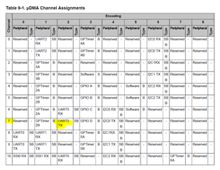
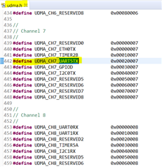
I am new to DMA and just had a basic understanding of the example in udma_demo, it uses UART1 and channel number is defined as

#define UDMA_CHANNEL_UART1TX    23

While I am going to use UART5 for Tx with DMA, and cannot find the definition for that, help please!

Regards!

Ping

  • Hi,

      You will need to refer to the uDMA chapter in the datasheet. UART5TX is mapped to channel 7. 

    Also see the udma.h header file for all the definitions.

  • Thanks for reply, Charles

    I understand the UART5 TX is mapped to Channel 7, but I need to pass the channel ID to the function uDMAChannelEnable( ), which requires a channel ID number like defined here - 

    //*****************************************************************************
    //
    // Channel numbers to be passed to API functions that require a channel number
    // ID.
    //
    //*****************************************************************************
    #define UDMA_CHANNEL_USBEP1RX 0
    #define UDMA_CHANNEL_USBEP1TX 1
    #define UDMA_CHANNEL_USBEP2RX 2
    #define UDMA_CHANNEL_USBEP2TX 3
    #define UDMA_CHANNEL_USBEP3RX 4
    #define UDMA_CHANNEL_USBEP3TX 5
    #define UDMA_CHANNEL_ETH0RX 6
    #define UDMA_CHANNEL_ETH0TX 7
    #define UDMA_CHANNEL_UART0RX 8
    #define UDMA_CHANNEL_UART0TX 9
    #define UDMA_CHANNEL_SSI0RX 10
    #define UDMA_CHANNEL_SSI0TX 11
    #define UDMA_CHANNEL_ADC0 14
    #define UDMA_CHANNEL_ADC1 15
    #define UDMA_CHANNEL_ADC2 16
    #define UDMA_CHANNEL_ADC3 17
    #define UDMA_CHANNEL_TMR0A 18
    #define UDMA_CHANNEL_TMR0B 19
    #define UDMA_CHANNEL_TMR1A 20
    #define UDMA_CHANNEL_TMR1B 21
    #define UDMA_CHANNEL_UART1RX 22
    #define UDMA_CHANNEL_UART1TX 23
    #define UDMA_CHANNEL_SSI1RX 24
    #define UDMA_CHANNEL_SSI1TX 25
    #define UDMA_CHANNEL_I2S0RX 28
    #define UDMA_CHANNEL_I2S0TX 29
    #define UDMA_CHANNEL_SW 30

    i.e. I pass 23 when I use UART1TX, when I need to use UART7TX, it is not here. By the datasheet, there are 89 possible peripheral share same channel number, how do i configure them please?

    Regards!

    Ping

  • You need to call uDMAChannelEnable(UDMA_CH7_UART5TX).

  • Hi, Charles

    I am a bit confused, do i need to call uDMAChannelAssign(UDMA_CH7_UART5TX) before enable the channel? as the UART5TX is not the default mapping in DMA Channel 7.  I still think I should enable channel 7 in uDMAChannelEnable(7), not uDMAChannelEnable(UDMA_CH7_UART5TX). as UDMA_CH7_UART5TX = 0x00020007. 

    Could you give me more complete code snips for using UART5TX please?

    Regards!

    Ping

  • Hi ping,

    Here is an example to use UART4TX. You can reference and adapt to other UART. 

    udma_demo_UART4_TX.c
    //*****************************************************************************
    //
    // udma_demo.c - uDMA example.
    //
    // Copyright (c) 2013-2017 Texas Instruments Incorporated.  All rights reserved.
    // Software License Agreement
    // 
    // Texas Instruments (TI) is supplying this software for use solely and
    // exclusively on TI's microcontroller products. The software is owned by
    // TI and/or its suppliers, and is protected under applicable copyright
    // laws. You may not combine this software with "viral" open-source
    // software in order to form a larger program.
    // 
    // THIS SOFTWARE IS PROVIDED "AS IS" AND WITH ALL FAULTS.
    // NO WARRANTIES, WHETHER EXPRESS, IMPLIED OR STATUTORY, INCLUDING, BUT
    // NOT LIMITED TO, IMPLIED WARRANTIES OF MERCHANTABILITY AND FITNESS FOR
    // A PARTICULAR PURPOSE APPLY TO THIS SOFTWARE. TI SHALL NOT, UNDER ANY
    // CIRCUMSTANCES, BE LIABLE FOR SPECIAL, INCIDENTAL, OR CONSEQUENTIAL
    // DAMAGES, FOR ANY REASON WHATSOEVER.
    // 
    // This is part of revision 2.1.4.178 of the EK-TM4C1294XL Firmware Package.
    //
    //*****************************************************************************
    
    #include <stdint.h>
    #include <stdbool.h>
    #include "inc/hw_ints.h"
    #include "inc/hw_memmap.h"
    #include "inc/hw_types.h"
    #include "inc/hw_uart.h"
    #include "driverlib/fpu.h"
    #include "driverlib/gpio.h"
    #include "driverlib/interrupt.h"
    #include "driverlib/pin_map.h"
    #include "driverlib/rom.h"
    #include "driverlib/rom_map.h"
    #include "driverlib/sysctl.h"
    #include "driverlib/systick.h"
    #include "driverlib/uart.h"
    #include "driverlib/udma.h"
    #include "utils/cpu_usage.h"
    #include "utils/uartstdio.h"
    #include "utils/ustdlib.h"
    
    //*****************************************************************************
    //
    //! \addtogroup example_list
    //! <h1>uDMA (udma_demo)</h1>
    //!
    //! This example application demonstrates the use of the uDMA controller to
    //! transfer data between memory buffers, and to transfer data to and from a
    //! UART.  The test runs for 10 seconds before exiting.
    //!
    //! UART0, connected to the ICDI virtual COM port and running at 115,200,
    //! 8-N-1, is used to display messages from this application.
    //
    //*****************************************************************************
    
    //****************************************************************************
    //
    // System clock rate in Hz.
    //
    //****************************************************************************
    uint32_t g_ui32SysClock;
    
    //*****************************************************************************
    //
    // The number of SysTick ticks per second used for the SysTick interrupt.
    //
    //*****************************************************************************
    #define SYSTICKS_PER_SECOND     100
    
    //*****************************************************************************
    //
    // The size of the memory transfer source and destination buffers (in words).
    //
    //*****************************************************************************
    #define MEM_BUFFER_SIZE         1024
    
    //*****************************************************************************
    //
    // The size of the UART transmit and receive buffers.  They do not need to be
    // the same size.
    //
    //*****************************************************************************
    #define UART_TXBUF_SIZE         65536
    #define UART_RXBUF_SIZE         256
    
    //*****************************************************************************
    //
    // The source and destination buffers used for memory transfers.
    //
    //*****************************************************************************
    static uint32_t g_ui32SrcBuf[MEM_BUFFER_SIZE];
    static uint32_t g_ui32DstBuf[MEM_BUFFER_SIZE];
    
    //*****************************************************************************
    //
    // The transmit  buffers used for the UART transfers.
    //
    //*****************************************************************************
    static uint8_t g_ui8TxBuf[UART_TXBUF_SIZE];
    
    //*****************************************************************************
    //
    // The count of uDMA errors.  This value is incremented by the uDMA error
    // handler.
    //
    //*****************************************************************************
    static uint32_t g_ui32uDMAErrCount = 0;
    
    //*****************************************************************************
    //
    // The count of times the uDMA interrupt occurred but the uDMA transfer was not
    // complete.  This should remain 0.
    //
    //*****************************************************************************
    static uint32_t g_ui32BadISR = 0;
    
    
    //*****************************************************************************
    //
    // The count of memory uDMA transfer blocks.  This value is incremented by the
    // uDMA interrupt handler whenever a memory block transfer is completed.
    //
    //*****************************************************************************
    static uint32_t g_ui32MemXferCount = 0;
    
    
    //*****************************************************************************
    //
    // The number of seconds elapsed since the start of the program.  This value is
    // maintained by the SysTick interrupt handler.
    //
    //*****************************************************************************
    static uint32_t g_ui32Seconds = 0;
    
    //*****************************************************************************
    //
    // The control table used by the uDMA controller.  This table must be aligned
    // to a 1024 byte boundary.
    //
    //*****************************************************************************
    #if defined(ewarm)
    #pragma data_alignment=1024
    uint8_t pui8ControlTable[1024];
    #elif defined(ccs)
    #pragma DATA_ALIGN(pui8ControlTable, 1024)
    uint8_t pui8ControlTable[1024];
    #else
    uint8_t pui8ControlTable[1024] __attribute__ ((aligned(1024)));
    #endif
    
    //*****************************************************************************
    //
    // The error routine that is called if the driver library encounters an error.
    //
    //*****************************************************************************
    #ifdef DEBUG
    void
    __error__(char *pcFilename, uint32_t ui32Line)
    {
    }
    #endif
    
    //*****************************************************************************
    //
    // The interrupt handler for the SysTick timer.  This handler will increment a
    // seconds counter whenever the appropriate number of ticks has occurred.  It
    // will also call the CPU usage tick function to find the CPU usage percent.
    //
    //*****************************************************************************
    void
    SysTickHandler(void)
    {
        static uint32_t ui32TickCount = 0;
    
        //
        // Increment the tick counter.
        //
        ui32TickCount++;
    
        //
        // If the number of ticks per second has occurred, then increment the
        // seconds counter.
        //
        if(!(ui32TickCount % SYSTICKS_PER_SECOND))
        {
            g_ui32Seconds++;
        }
    }
    
    //*****************************************************************************
    //
    // The interrupt handler for uDMA errors.  This interrupt will occur if the
    // uDMA encounters a bus error while trying to perform a transfer.  This
    // handler just increments a counter if an error occurs.
    //
    //*****************************************************************************
    void
    uDMAErrorHandler(void)
    {
        uint32_t ui32Status;
    
        //
        // Check for uDMA error bit
        //
        ui32Status = ROM_uDMAErrorStatusGet();
    
        //
        // If there is a uDMA error, then clear the error and increment
        // the error counter.
        //
        if(ui32Status)
        {
            ROM_uDMAErrorStatusClear();
            g_ui32uDMAErrCount++;
        }
    }
    
    //*****************************************************************************
    //
    // The interrupt handler for uDMA interrupts from the memory channel.  This
    // interrupt will increment a counter, and then restart another memory
    // transfer.
    //
    //*****************************************************************************
    void
    uDMAIntHandler(void)
    {
        uint32_t ui32Mode;
    
        //
        // Check for the primary control structure to indicate complete.
        //
        ui32Mode = ROM_uDMAChannelModeGet(UDMA_CH19_UART4TX);
        if(ui32Mode == UDMA_MODE_STOP)
        {
            //
            // Increment the count of completed transfers.
            //
            g_ui32MemXferCount++;
    
            //
            // Configure it for another transfer.
            //
            ROM_uDMAChannelTransferSet(UDMA_CH19_UART4TX, UDMA_MODE_AUTO,
                                         g_ui32SrcBuf, g_ui32DstBuf,
                                         MEM_BUFFER_SIZE);
    
            //
            // Initiate another transfer.
            //
            ROM_uDMAChannelEnable(UDMA_CH19_UART4TX);
            ROM_uDMAChannelRequest(UDMA_CH19_UART4TX);
        }
    
        //
        // If the channel is not stopped, then something is wrong.
        //
        else
        {
            g_ui32BadISR++;
        }
    }
    
    //*****************************************************************************
    //
    // The interrupt handler for UART4.  This interrupt will occur when a DMA
    // transfer is complete using the UART4 uDMA channel.  It will also be
    // triggered if the peripheral signals an error.  This interrupt handler will
    // switch between receive ping-pong buffers A and B.  It will also restart a TX
    // uDMA transfer if the prior transfer is complete.  This will keep the UART
    // running continuously (looping TX data back to RX).
    //
    //*****************************************************************************
    uint32_t uart_interrupt_enterred = 0;
    uint32_t uart_dma_done = 0;
    
    void
    UART4IntHandler(void)
    {
    
        uint32_t ui32Status;
        uint32_t ui32Mode;
    
        uart_interrupt_enterred++;
    
        //
        // Read the interrupt status of the UART.
        //
    
        ui32Status = ROM_UARTIntStatus(UART4_BASE, 1);
    
        //
        // Clear any pending status, even though there should be none since no UART
        // interrupts were enabled.  If UART error interrupts were enabled, then
        // those interrupts could occur here and should be handled.  Since uDMA is
        // used for both the RX and TX, then neither of those interrupts should be
        // enabled.
        //
        ROM_UARTIntClear(UART4_BASE, ui32Status);
    
        //
        // Check the DMA control table to see if the ping-pong "A" transfer is
        // complete.  The "A" transfer uses receive buffer "A", and the primary
        // control structure.
        //
        //
        ui32Mode = ROM_uDMAChannelModeGet(UDMA_CH19_UART4TX | UDMA_PRI_SELECT);


        //
        // If the UART4 DMA TX channel is disabled, that means the TX DMA transfer
        // is done.
        //
    
        if(!ROM_uDMAChannelIsEnabled(UDMA_CH19_UART4TX))
        {
        	uart_dma_done++;
    
            //
            // Start another DMA transfer to UART4 TX.
            //
            ROM_uDMAChannelTransferSet(UDMA_CH19_UART4TX | UDMA_PRI_SELECT,
                                       UDMA_MODE_BASIC, g_ui8TxBuf,
                                       (void *)(UART4_BASE + UART_O_DR),
                                       sizeof(g_ui8TxBuf));
    
            //
            // The uDMA TX channel must be re-enabled.
            //
            ROM_uDMAChannelEnable(UDMA_CH19_UART4TX);
        }
    }
    
    //*****************************************************************************
    //
    // Initializes the UART4 peripheral and sets up the TX and RX uDMA channels.
    // The UART is configured for loopback mode so that any data sent on TX will be
    // received on RX.  The uDMA channels are configured so that the TX channel
    // will copy data from a buffer to the UART TX output.  And the uDMA RX channel
    // will receive any incoming data into a pair of buffers in ping-pong mode.
    //
    //*****************************************************************************
    void
    InitUART4Transfer(void)
    {
        uint_fast16_t ui16Idx;
    
        //
        // Enable the peripherals used by this example.
        //
        ROM_SysCtlPeripheralEnable(SYSCTL_PERIPH_GPIOA);
    
        //
        // Set GPIO A0 and A1 as UART pins.
        //
        GPIOPinConfigure(GPIO_PA3_U4TX);
        ROM_GPIOPinTypeUART(GPIO_PORTA_BASE, GPIO_PIN_3);
    
        //
        // Fill the TX buffer with a simple data pattern.
        //
        for(ui16Idx = 0; ui16Idx < UART_TXBUF_SIZE; ui16Idx++)
        {
            g_ui8TxBuf[ui16Idx] = ui16Idx;
        }
    
        //
        // Enable the UART peripheral, and configure it to operate even if the CPU
        // is in sleep.
        //
        ROM_SysCtlPeripheralEnable(SYSCTL_PERIPH_UART4);
        ROM_SysCtlPeripheralSleepEnable(SYSCTL_PERIPH_UART4);
    
        //
        // Configure the UART communication parameters.
        //
        ROM_UARTConfigSetExpClk(UART4_BASE, g_ui32SysClock, 115200,
                                UART_CONFIG_WLEN_8 | UART_CONFIG_STOP_ONE |
                                UART_CONFIG_PAR_NONE);
    
        //
        // Set both the TX and RX trigger thresholds to 4.  This will be used by
        // the uDMA controller to signal when more data should be transferred.  The
        // uDMA TX and RX channels will be configured so that it can transfer 4
        // bytes in a burst when the UART is ready to transfer more data.
        //
        ROM_UARTFIFOLevelSet(UART4_BASE, UART_FIFO_TX4_8, UART_FIFO_RX4_8);
    
        //
        // Enable the UART for operation, and enable the uDMA interface for both TX
        // and RX channels.
        //
        ROM_UARTEnable(UART4_BASE);
        ROM_UARTDMAEnable(UART4_BASE, UART_DMA_TX);
    
        //
        // Put the attributes in a known state for the uDMA UART4TX channel.  These
        // should already be disabled by default.
        //
        uDMAChannelAssign(UDMA_CH19_UART4TX);
        ROM_uDMAChannelAttributeDisable(UDMA_CH19_UART4TX,
                                        UDMA_ATTR_ALTSELECT |
                                        UDMA_ATTR_HIGH_PRIORITY |
                                        UDMA_ATTR_REQMASK);
    
        //
        // Set the USEBURST attribute for the uDMA UART TX channel.  This will
        // force the controller to always use a burst when transferring data from
        // the TX buffer to the UART.  This is somewhat more efficient bus usage
        // than the default which allows single or burst transfers.
        //
        ROM_uDMAChannelAttributeEnable(UDMA_CH19_UART4TX, UDMA_ATTR_USEBURST);
    
        //
        // Configure the control parameters for the UART TX.  The uDMA UART TX
        // channel is used to transfer a block of data from a buffer to the UART.
        // The data size is 8 bits.  The source address increment is 8-bit bytes
        // since the data is coming from a buffer.  The destination increment is
        // none since the data is to be written to the UART data register.  The
        // arbitration size is set to 4, which matches the UART TX FIFO trigger
        // threshold.
        //
        ROM_uDMAChannelControlSet(UDMA_CH19_UART4TX | UDMA_PRI_SELECT,
                                  UDMA_SIZE_8 | UDMA_SRC_INC_8 |
                                  UDMA_DST_INC_NONE |
                                  UDMA_ARB_4);
    
        //
        // Set up the transfer parameters for the uDMA UART TX channel.  This will
        // configure the transfer source and destination and the transfer size.
        // Basic mode is used because the peripheral is making the uDMA transfer
        // request.  The source is the TX buffer and the destination is the UART
        // data register.
        //
        //
        ROM_uDMAChannelTransferSet(UDMA_CH19_UART4TX | UDMA_PRI_SELECT,
                                   UDMA_MODE_BASIC, g_ui8TxBuf,
                                   (void *)(UART4_BASE + UART_O_DR),
                                   sizeof(g_ui8TxBuf));
    
        //
        // Now both the uDMA UART TX and RX channels are primed to start a
        // transfer.  As soon as the channels are enabled, the peripheral will
        // issue a transfer request and the data transfers will begin.
        //
        ROM_uDMAChannelEnable(UDMA_CH19_UART4TX);
    
        //
        // Enable the UART DMA TX/RX interrupts.
        //
        ROM_UARTIntEnable(UART4_BASE, UART_INT_DMATX);
    
        //
        // Enable the UART peripheral interrupts.
        //
        ROM_IntEnable(INT_UART4);
    }


    //*****************************************************************************
    //
    // Configure the UART and its pins.  This must be called before UARTprintf().
    //
    //*****************************************************************************
    void
    ConfigureUART(void)
    {
        //
        // Enable the GPIO Peripheral used by the UART.
        //
        ROM_SysCtlPeripheralEnable(SYSCTL_PERIPH_GPIOA);
    
        //
        // Enable UART0
        //
        ROM_SysCtlPeripheralEnable(SYSCTL_PERIPH_UART0);
        ROM_SysCtlPeripheralSleepEnable(SYSCTL_PERIPH_UART0);
    
        //
        // Configure GPIO Pins for UART mode.
        //
        ROM_GPIOPinConfigure(GPIO_PA0_U0RX);
        ROM_GPIOPinConfigure(GPIO_PA1_U0TX);
        ROM_GPIOPinTypeUART(GPIO_PORTA_BASE, GPIO_PIN_0 | GPIO_PIN_1);
    
        //
        // Initialize the UART for console I/O.
        //
        UARTStdioConfig(0, 115200, g_ui32SysClock);
    }
    
    //*****************************************************************************
    //
    // This example demonstrates how to use the uDMA controller to transfer data
    // between memory buffers and to and from a peripheral, in this case a UART.
    // The uDMA controller is configured to repeatedly transfer a block of data
    // from one memory buffer to another.  It is also set up to repeatedly copy a
    // block of data from a buffer to the UART output.  The UART data is looped
    // back so the same data is received, and the uDMA controlled is configured to
    // continuously receive the UART data using ping-pong buffers.
    //
    // The processor is put to sleep when it is not doing anything, and this allows
    // collection of CPU usage data to see how much CPU is being used while the
    // data transfers are ongoing.
    //
    //*****************************************************************************
    int
    main(void)
    {
    
        //
        // Set the clocking to run directly from the crystal at 120MHz.
        //
        g_ui32SysClock = MAP_SysCtlClockFreqSet((SYSCTL_XTAL_25MHZ |
                                                 SYSCTL_OSC_MAIN |
                                                 SYSCTL_USE_PLL |
                                                 SYSCTL_CFG_VCO_480), 120000000);
    
        //
        // Enable peripherals to operate when CPU is in sleep.
        //
        ROM_SysCtlPeripheralClockGating(true);
    
        //
        // Enable the GPIO port that is used for the on-board LED.
        //
        ROM_SysCtlPeripheralEnable(SYSCTL_PERIPH_GPION);
    
        //
        // Enable the GPIO pins for the LED (PN0).
        //
        ROM_GPIOPinTypeGPIOOutput(GPIO_PORTN_BASE, GPIO_PIN_0);
    
        //
        // Initialize the UART.
        //
        ConfigureUART();
    	UARTprintf("\033[2J\033[H");
        UARTprintf("uDMA for UART4TX Example \n");
    
        //
        // Enable the uDMA controller at the system level.  Enable it to continue
        // to run while the processor is in sleep.
        //
        ROM_SysCtlPeripheralEnable(SYSCTL_PERIPH_UDMA);
        ROM_SysCtlPeripheralSleepEnable(SYSCTL_PERIPH_UDMA);
    
        //
        // Enable the uDMA controller error interrupt.  This interrupt will occur
        // if there is a bus error during a transfer.
        //
        ROM_IntEnable(INT_UDMAERR);
    
        //
        // Enable the uDMA controller.
        //
        ROM_uDMAEnable();
    
        //
        // Point at the control table to use for channel control structures.
        //
        ROM_uDMAControlBaseSet(pui8ControlTable);
    
    
        //
        // Initialize the uDMA UART transfers.
        //
        InitUART4Transfer();
    
        //
        // Loop forever with the CPU not sleeping, so the debugger can connect.
        //
        while(1)
        {
    			  //
            // Turn on the LED.
            //
            GPIOPinWrite(GPIO_PORTN_BASE, GPIO_PIN_0, GPIO_PIN_0);
    
            //
            // Delay for a bit.
            //
            SysCtlDelay(g_ui32SysClock / 20 / 3);
    
            //
            // Turn off the LED.
            //
            GPIOPinWrite(GPIO_PORTN_BASE, GPIO_PIN_0, 0);
    
            //
            // Delay for a bit.
            //
            SysCtlDelay(g_ui32SysClock / 20 / 3);
        }
    }
    

  • Thank you for sending it, I tried sending both 19 and UDMA_CH19_UART4TX works where channel ID is needed. Just that when define the UART1TX and other ones, different format is very confusing while channel numbers are only valid from 0-31.

    Thanks for your help!